
- Forum Listing
- Marketplace
- Advanced Search
- The Minivan Mopar Garage
- 4th Generation Chrysler Minivans: 2001-2007

How to change transmission range sensor on auto tranny
- Add to quote
hello, hopefully someone in here can help me, i need to change the transmission range sensor on my 2002 3.3L auto grand voyager. i have had a problem where my van went into limp mode and it wouldnt change out of second gear, after trying manu different things myself i took it to a garage who mending some wiring on the gearbox and identified a fault code saying that the TRS had gone down. can you someone give me a step by step guide on the best way to change the sensor? i know through googling that the sump and filter need to be removed and the oil drained before removing a valve body, i just dont to be removing parts that i dont need to and causing myself more work. thanks in advance, Scott.
FSM said: TRS REMOVAL (1) Remove valve body assembly from transaxle. (Refer to 21 - TRANSMISSION/TRANSAXLE/AUTO- MATIC - 41TE/VALVE BODY - REMOVAL) (2) Remove transmission range sensor retaining screw and remove sensor from valve body (Fig. 330). (3) Remove TRS from manual shaft. VALVE BODY REMOVAL NOTE: If valve body is replaced or reconditioned, the TCM Quick Learn Procedure must be per- formed. (Refer to 8 - ELECTRICAL/ELECTRONIC CONTROL MODULES/TRANSMISSION CONTROL MODULE - STANDARD PROCEDURE) (1) Disconnect battery negative cable. (2) Disconnect gearshift cable from manual valve lever. (3) Remove manual valve lever from manual shaft. (4) Raise vehicle on hoist. (5) Remove oil pan bolts (Fig. 332). (6) Remove oil pan (Fig. 333). (7) Remove oil filter (Fig. 334). (8) Remove the valve body-to-transaxle case bolts (Fig. 335). (9) Remove park rod rollers from guide bracket and remove valve body from transaxle (Fig. 336) (Fig. 337). CAUTION: The valve body manual shaft pilot may distort and bind the manual valve if the valve body is mishandled or dropped. DISASSEMBLY NOTE: If valve body assembly is being recondi- tioned, the PCM/TCM Quick Learn Procedure must be performed. (Refer to 8 - ELECTRICAL/ELEC- TRONIC CONTROL MODULES/TRANSMISSION CONTROL MODULE - STANDARD PROCEDURE) (1) Remove manual shaft seal (Fig. 338). (2) Remove Transmission Range Sensor retaining screw (Fig. 339). (3) Remove Manual Shaft/Rooster Comb and Transmission Range Sensor (Fig. 340). Click to expand...
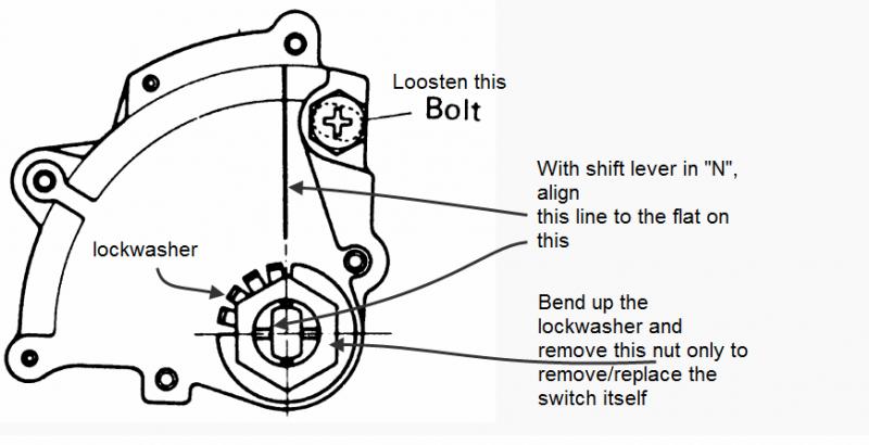
fsm said: TRANSMISSION RANGE SENSOR DESCRIPTION The Transmission Range Sensor (TRS) is mounted to the top of the valve body inside the transaxle and can only be serviced by removing the valve body. The electrical connector extends through the transaxle case (Fig. 328). The Transmission Range Sensor (TRS) has four switch contacts that monitor shift lever position and send the information to the PCM/TCM. The TRS also has an integrated temperature sen- sor (thermistor) that communicates transaxle tem- perature to the TCM and PCM (Fig. 329). OPERATION The Transmission Range Sensor (TRS) (Fig. 328) communicates shift lever position (SLP) to the PCM/ TCM as a combination of open and closed switches. Each shift lever position has an assigned combination of switch states (open/closed) that the PCM/TCM receives from four sense circuits. The PCM/TCM inter- prets this information and determines the appropriate transaxle gear position and shift schedule. Since there are four switches, there are 16 possible combinations of open and closed switches (codes). Seven of these codes are related to gear position and three are recognized as ªbetween gearº codes. This results in six codes which should never occur. These are called ªinvalidº codes. An invalid code will result in a DTC, and the PCM/TCM will then determine the shift lever position based on pressure switch data. This allows reasonably normal transmission opera- tion with a TRS failure. TRS SWITCH STATES SLP T42 T41 T3 T1 P CL CL CL OP R CL OP OP OP N CL CL OP CL OD OP OP OP CL 3 OP OP CL OP L CL OP CL CL Click to expand...

atoman said: Sump needs to be removed? (does 'sump' have a different meaning on the other side of the pond or was that a joke?) Click to expand...
I currently have the valvebody out to swap in some Sonnax torque converter regulator valves. Is it worth replacing the range switch "while I'm in there"? This is on an '03 with 91k miles on it.
TRS failures on these boxes are not common. I wouldn't do it unless there are signs of excessive wear or future problem (cracked connector, corrosion, loose shaft, etc) Also, aftermarket TRS may or may not be of OE quality...
My 2 cents I found this thread very helpful in replacing the TRS in my 05 T&C. I thought I'd add a few points I learned in the process that may help someone else. The problem I was having that led to job this was an intermittent no-start condition: turn the ignition switch, the starter would engage and crank either momentarily or not at all. The PRLD dash lights were acting strangely: All lit up at once or the wrong gear position lit up, sometimes would start in P but not N- or vice versa. There were no trouble codes and with this vehicle's ECM it can be difficult to diagnose any electrical problem without a scan tool (which most DIYers don't have). I hate throwing parts at any problem so I search Google for forums, youTube videos, obscure posts, etc. I gathered enough nuggets to determine that the TRS was likely causing my problem. One thing to be aware of when following instructions you find while searching the net is to be sure you know what transmission model is in your vehicle- otherwise you may go down the wrong rabbit hole and get frustrated. Easiest way is probably call a dealer and ask the parts department- they'll need your VIN. If you're a weekend warrior you may have to hunt on your own. I found mine, 41TE/A604 here: http://www.txchange.com/id.htm The posts by FSM were very helpful but without the referenced diagrams or a link to the source for the procedure (likely the service manual), there were pieces of the puzzle still missing. For example, before removing the linkage from the manual lever to the shaft on the trans, make a match mark on both so when you re-attach at the end you're sure both the lever and the trans are in the same position ie: Park. After you remove the linkage (step 3) and before you remove the valve body it is necessary to put a wrench on the rotate the shaft to to the lock position which is one click beyond the lowest gear (past what you can do with the manual lever inside the van). Without doing this the valve body will not come out or go back in. I think that the description in step 9 is a bit confusing when saying to remove the "park rod rollers from the guide bracket". I found that rotating the shaft to the lock position seats and locks the park rod securely for valve body removal and reinstall. The valve body has many screws facing you but to remove it just unscrew the hex heads and leave the torx heads alone. You'll have to remove the harness connector just forward of the manual shaft before pulling down the valve body- this connector is attached to the TRS. When I freed the valve body there was a splash in my fluid catch pan which turned out to be the overdrive and underdrive accumulator pistons and springs. The pistons appear to be interchangable but the springs are not: one has a nested spring (one inside the other) and I deduced which went where by looking at the valve body where I saw slight wear marks where the springs bear on it (I think the double spring was at the forward position). At re-install of the valve body you have to put the pistons and springs back in the case (springs toward the valve body) and hold them there with one hand while inserting the valve body- pull your fingers off the pistons when the valve body contacts them and they will stay in the case. Once the valve body is bolted and before re-attaching the shift linkage to the shaft, rotate the shaft back to its Park position and confirm with the match marks you made before disconnecting. Here are links to pages I found that helped with all of this. Good luck: https://www.uscars.biz/uscars/extras-documents/ATRA_Chrysler_41TE_604_Rebuild_Procedures.pdf (very comprehensive- look for pages concerning valve body) https://oppositelock.kinja.com/tag/41te (nicely organized in sections, lots of pictures with comments below) https://www.youtube.com/watch?v=dpCNgEH4eLA https://www.youtube.com/watch?v=OO_AwBsrxpw (for 62TE if you have it)

- Disconnect shifter linkage.
- Rotate transmission shifter shaft all the way clockwise (one click past L).
- Remove shifter linkage arm from the shifter shaft. Ensure this shaft and surrounding area is clean and free dirt, debris, rust and corrosion. This shaft will be removed downward with valve body.
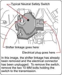
- Disconnect the electrical plug at the forward LH corner of the transmission as viewed from above. (This would be the passenger side on a RH drive vehicle) (driver side on US vehicle)
- Drain/remove oil pan and filter.
- Remove all bolts (10mm socket) on the valve body.
- Slowly and carefully lower the valve body down out of the transmission. Do not force anything. Slight and careful prying may be required. Valve body will get hung up by the shifter PARK internal linkage if the shift shaft is not fully rotated CW. I believe that this shift shaft seal (p/n 92349) will be the greatest resistance to valve body removal as long as shaft is fully rotated past low L.
- There are two solenoids and their respective springs that will likely be atop the valve body. Note their position, orientation, and associated spring configuration. If they are sitting not atop the valve body, locate and remove then from transmission body. Again, note position and configuration.
- There is also a 2-4 clutch piston to valve body seal p/n 92342 that sits atop the valve body. Ensure this is in position and secure. Ensure this is in position, pliable and serviceable when you reinstall the valve body
- Install new components and reverse procedure to reinstall. Ensure shift shaft seal is serviceable or replace (again p/n 92349).
- You may use (sparingly) petrolatum (Vaseline petroleum jelly) during installation to hold parts in position such as accumulators and springs (only as much as required). There is also a product called "Assembly Goo" that is used in place of petrolatum. They use petrolatum in the factory for assembly and I believe it is still compatible with the transmission fluid. Lubricate the shift shaft seal and shift position indicator connector o-ring with appropriate trans fluid. Again, ensure the parking pawl linkage is in its storage position before valve body install (shaft fully rotated CW past the low position [the last indent on the rooster comb])
- Some force may be required to reinstall the shift shaft into the transmission body. Tapping with soft blow hammer or heal of the hand (directly below the shaft position on valve body bottom)
- Install all bolts to just snug, and then torque to 22Nm / 23 Ft lb.
- Reintall new filter oring and filter.
- Clean pan magnet and ensure placement near two dimples in oil pan. Reinstall oil pan (sump) and torque to 19Nm / 14 Ft lb.
- ?
- 573.8K posts
- 80.9K members
Top Contributors this Month

- Ciudad de México
- +52 1 5521862459
- [email protected]
- 🏁PÁGINA PRINCIPAL 🏁
- ⚙INGENIERÍA Y MECANICA⚙
- 📝CURSO DE ESPECIALIZACIÓN DIAGNOSTICO Y PROGRAMACIÓN📝
- 🛠SERVICIO Y CONSULTORIAS📐

INGENIERÍA Y MECÁNICA AUTOMOTRIZ
Donde se fusiona la Ingeniería y la mecánica Automotriz
¿Qué es el sensor TRS (Transmission Range) y cómo funciona?

El sensor de posición de la transmisión, también conocido como sensor de rango de transmisión, es un sensor electrónico que proporciona una entrada de posición al Módulo de control del tren motriz (PCM) para que la transmisión pueda ser controlada correctamente por el PCM de acuerdo con la posición ordenada por el sensor.
El sensor de rango de la transmisión a veces también se denomina interruptor de estacionamiento / neutral o interruptor de seguridad. Se comunica con el módulo de control de transmisión del vehículo y el PCM, y está conectado a la válvula manual de transmisión.
El interruptor de rango de la transmisión identifica si la palanca selectora está en estacionamiento o en neutral y envía la señal al módulo de control de la transmisión. Lo hace para garantizar que el vehículo arranque en posición de estacionamiento y neutral e informar al PCM sobre la posición de la palanca de cambios. El PCM envía una referencia de voltaje al sensor, mientras que el sensor envía un voltaje diferente al PCM, dependiendo de la palanca de cambios en la que se encuentre.
La rotación de la corona cambia el campo magnético, que, a su vez, cambia el voltaje en el sensor de rango de transmisión. Estas señales de voltaje son enviadas a la unidad de control por el sensor de rango de transmisión.
Fallos comunes DTC
- Código de diagnóstico de problemas (DTC) El código P0705 significa «Mal funcionamiento del circuito del sensor de rango de la transmisión (entrada PRNDL)». Se activa cuando el sensor de rango de transmisión no puede enviar datos o proporciona una entrada errónea a los módulos de control de transmisión (TCM) o de control del tren motriz (PCM).
- El código de error P0706 ocurre cuando la transmisión no recibe datos claros del sensor de rango de transmisión, o el voltaje de retorno no es el que se supone que es. Esto generalmente sucede cuando el vehículo se está moviendo y lee que el vehículo está viajando a una velocidad que no coincide con la lectura del PCM para la posición de cambio actual, como cuando viaja a cualquier velocidad cuando la transmisión lee e informa que todavía está en estacionamiento o posición neutral.
- Código de error P0707 : Entrada baja en el circuito del sensor de rango de transmisión
- Código de error P0708 : Entrada alta en el circuito del sensor de rango de transmisión
- Código de error P0709 : circuito del sensor de rango de transmisión intermitente
- Código de error P0814 : circuito de visualización del rango de transmisión
- Código de error P0819 : Cambio de cambio hacia arriba y hacia abajo para correlación del rango de transmisión
29 thoughts on “ ¿Qué es el sensor TRS (Transmission Range) y cómo funciona? ”
Muy bueno, así es como se quitan las dudas eso está magnífico ,saludos
Será difícil de encontrar este tipo de sensores en las tiendas de repuestos?
Nosotros contamos con estas piezas
Yo tengo un Civic 2012…
Mi carro cuando está en parking el velocímetro de la pantalla marca una velocidad de 10 km/h. Cuando yo quiero pasar el cambio de Parking a Reversa el cambio no le entra (lo más seguro el carro detecta que el carro va en movimiento y por esa razón no entra el cambio), cuando yo coloco en D el carro a veces hace bien los cambios y otra veces se compresiona el motor porque no hace el cambio, a veces tienen que subir mucho las revoluciones para hacer el cambio. Cuando está en D y me paro el velocímetro ahí baja a Cero, si en ese momento pongo la reversa ahí si me funciona bien la reversa. Que podrá ser????
La falla la tengo después de un acidente que tuve en carretera
Lo mejor es cotizarlo en Amazon, porque comprarlo usado o reparado servira un tiempo, quiza por el modelo del auto no se encuentra en las ventas de repuestos, mi kia 2001 encontre que funciona el mismo del año 2010.
Cómo cuánto costara
entre 1000 a 3000MXN
Este sensor le queda a un Renault Megane 2003 que solo arranca en Neutral?
Primero se debe de diagnosticar correctamente
ESTE SENSOR TRS O VALVULA SELECTORA..PUEDE PROVOCAR QUE LA REVERSA EN MI CARRO CAE SUPER TARDADA?
Talvez si sea este sensor su problema
El arnes y conector de en limpiarase con limpia contactos, el error muchas veces que les entra agua cuando se lava el motor, y se van oxidando y deteriorando.
cuando pongo D o R y a N, en ralentí produce un tirón suave y acopla D o R. esto es falla del sensor trs? luego dde eso la caja cvt funciona optima! gracias
Hay que diagnosticar
Por este sensor podría no funcionar el botón de overdrive, no se desactiva ?
Ese es otro sensor que va conectado a la caja, no tiene nada que ver con este, puede ser el switch que esta en la palanca o sea ese botoncito que no desconecta. Ya me sucedio y solo fue de buscar otra palanca con switch.
Agradecido estimado maestro por colaborar en la capacitación técnica automotriz espero que todos los colegas que los siguen sepan valorar sin ego y con humildad el sus publicaciónes. Saludos Desde la Habana cuba
hola. es cierto q si el cable de la caja automatica no esta conectado…..el carro no arranca
Es correcto
Qué fallas hace ese sensor trs en la transmisión del sebring 2007 2.4l?
No selección de velocidades
Golpe en la caja de trasmición cuando cambio de P a D en CIVIC 2002 automático, podría ser el sensor ?
Tengo un cirrus 2004 y me marco el codigo P0706 despues de cambiar la caja de solenoides. El consumo de combustible ha mejorado, el arranque es «normal» (no es tan rapido pero no se queda quieto) y antes me marcaba codigo P0740, despues de cambiar la caja de solenoides me marca P0706, cual puede ser la falla?
Hola Buenas tardes, disculpe tengo un stratus 2.4 turbo h.o 2005, el selector de cambios en el tablero aparece seleccionando todas las velocidades al momento que esta en P, sin embargo al cambiar a D o R deja de seleccionar todas y solo selecciona a la cual cambiaste, si entran las velocidades pero me llama la atención el echo de que en P selecciona todas las velocidades… Contaran ustedes con ese sensor para el modelo de mi coche y que precio tiene por favor
Hola Buenas tardes …. Tengo un astra H 2007 1.8L europeo, cuando circulo a cierta velocidad y freno tarda en cambiar la velocidad…. es decir, en el clúster indica D3, acelero y no avanza…. hasta que cambia a la velocidad D2…. y un par de veces se queda en D4…. tengo que apagar el carro poner en parking y vuelve a funcionar…. sera que tengo que remplazar este sensor???? Agradezco de antemano su comentario
buenas noches disculpe ustedes me podrian vender el tr original de una ford f150 modelo 97 8cilindros motor 5.4 es que el que trae le anda fallando y me dice el macanico que no lo a podido conceguir
Deja una respuesta Cancelar la respuesta
Tu dirección de correo electrónico no será publicada. Los campos obligatorios están marcados con *
Comentario *
Correo electrónico *
Guarda mi nombre, correo electrónico y web en este navegador para la próxima vez que comente.
Add your answer here.
Check out some similar questions.
Hello, I replaced the BCM in my 1998 Plymouth Grand Voyager with a used one from a salvage yard. As soon as we re-connected the battery, the alarm starting going off ( we did not even know the van had a security system as the alarm has never gone off and we do not have the keyless remote ) We...
Can anyone please tell me where to find the "brain" from my transmission? We were told in the firewall, but cannot find this part. Can anyone give me a brief description of where to look? Thanks!
Replaced the engine and tranny on my 85 Voyager with known good units. The van now will not go into reverse or forward. Put in the required amount of fluid and have a good steady flow from the tranny coolant hose when disconnected to test with the engine running. When going from all different...
- ASK A QUESTION
- REPAIR GUIDES
- BECOME A MEMBER
- LOG IN Login with Facebook OR Remember me NOT A MEMBER? FORGOT PASSWORD?
- PRIVACY POLICY
- TERMS AND CONDITIONS
- Transmission
- Replace/Remove
Transmission sensors
- 2001 CHRYSLER VAN

- 19,053 POSTS

Please login or register to post a reply.
Related transmission replace/remove content, 2002 chrysler t&c auto trans fault code p740.

Transmission Code
Sponsored links.

- Contact •
- Help •
- About •
- Privacy Policy •
- Terms & Conditions
- 1-888-511-3595
- Chrysler Parts
- Dodge Parts
- Accessories
- Login/Register
- Track Order
- Help Center
Genuine Chrysler Voyager Automatic Transmission Shift Position Sensor Switch
Enter your vehicle info to find more parts and verify fitment.
- Select Vehicle by VIN
- Select Vehicle by Model
1 Automatic Transmission Shift Position Sensor Switch found

Chrysler Voyager Sensor-Transmission Range
- Other Name : Sensor Transmission Range
- Replaces : 4659676, 4659676AB
- 2000-2003 Chrysler Voyager | Base, EC, LX, SE | 4 Cyl 2.4L, 6 Cyl 3.0L, 6 Cyl 3.3L, 6 Cyl 3.8L
Related Chrysler Voyager Parts

American Voyager Association
We welcome all Voyagers (those who Voyage) whether you ride a Kawasaki Voyager or not, all brands are welcomed to join!
Skip to content
- Home Voyager Model Forums Tech Tips - Voyager XII (1200 Four)
- Join the AVA today (Opens a new tab)
- Make a Donation (Opens a new tab)
- Forum Registration (Opens a new tab)
- 2024 Rally Preview (Opens a new tab)
- 2023 Rally Closing Video (Opens a new tab)
water tempature sensor replacement
Moderators: the2knights , Highway Rider
Post by 6ft1_grand » Mon Mar 16, 2015 2:15 am

Re: water tempature sensor replacement
Post by debron » Mon Mar 16, 2015 4:05 am
Post by 6ft1_grand » Mon Mar 16, 2015 12:14 pm
Post by debron » Mon Mar 16, 2015 2:53 pm
Post by 6ft1_grand » Wed Mar 18, 2015 12:36 am
Return to “Tech Tips - Voyager XII (1200 Four)”
- Past Rallies and Next Rally--Next Rally Is In : Blairsville, Georgia
- ↳ 34th Annual AVA Rally Blairsville, GA. June 17th - 20th 2024
- ↳ 33rd Annual AVA Rally Shelburne, NH. June 19th - 22nd 2023
- ↳ Past AVA Rallys
- ↳ 32nd Annual AVA Rally Flagstaff, AZ. June 20th - 23rd 2022
- ↳ 31st Annual AVA Rally Springfield, MO. June 14-17, 2021
- ↳ Our Annual AVA Rally North Conway, NH. June 22-25, 2020 was cancelled
- ↳ 30th Annual AVA Rally Summersville WV. June 24-27 2019
- ↳ 29th Annual AVA Rally Kerrville Tx. June 25-28 2018
- ↳ 28th Annual AVA Rally Nashville In. June 21-19 2017
- ↳ 27th Annual AVA Rally Hurley Wi. June 20-23, 2016
- ↳ 26th Annual AVA Rally Estes Park Co. June 22-25, 2015
- ↳ 25th Annual Ava Rally Ashville Nc. July 7-10-2014
- ↳ 24th Annual AVA Rally Logan Oh July 8-11-2013
- Forum/Classified Ad Use/General Chat/Groups
- ↳ General Chat
- ↳ Forum/Classified Ads Use Questions
- ↳ Motorcycles for Sale
- ↳ Part for sale
- ↳ Parts Wanted
- Voyager Model Forums
- ↳ General - Voyager XII (1200 Four)
- ↳ Tech Tips - Voyager XII (1200 Four)
- ↳ General - Voyager 1300 Six
- ↳ Tech Tips - Voyager 1300 Six
- ↳ General - Voyager 1700 V-Twin
- ↳ Tech Tips - Voyager 1700 V-Twin
- ↳ AVA Voyagers 1300 1200 and 1700 Tech Center
- Other Brands/Misc.
- ↳ All Other Brands General Forum
- ↳ Travel Reports, Ideas, Questions, Suggestions
- ↳ Trailers/Trailer Tech
- ↳ Poll Forum
- AVA Express Flag
- ↳ AVA Express Flag
- All times are UTC
- Delete cookies
Powered by phpBB ® Forum Software © phpBB Limited
Privacy | Terms
Solo en Transmisión

- Supermercado
- Mercado Play Gratis

Sensor Switch Tr Peugeot Clio Platina Megane Transmision Dpo
Envío gratis

Sensor Tr A604 Mopar Puntas Planas Voyager Cirrus Neon...

Sensor A604 Tr Switch Puntas Planas Voyager Neon Cirrus

Sensor Tr Voyager Pines Redondos Swich Parking Neutral

Juego Sensores Entrada Salida A604 Voyaguer, Neon, Stratus

Sensores De Velocidad In Out A604 Nuevos Neon Voyager

Sensores Transmision A604 2 Pzas Entrada/salida Voyager

Sensor Neutral O Rango Original Stratus Cirrus Neon Voyager
por STRASSER

Sensores Velocidad In Out A604 Nuevos Voyager Neon Stratus

Tr Pines Planos Transmisión Automatica A604 604 Voyager

Switch A604 Tr Rangos Pin Redondo Eclipse Voyager Neon

Sensor Tr Mlps Transmisión Automáti Attitude 1.4l 1.6l 06-11

Sensor Neutral Tr Parking Suzuki Forenza 2007

Sensor Presión Transmisión Pacifica 200 Avenger Voyager

Tr Transmisión A604 Switch Nuevo Neon Voyager Mitsubishi

Tr A604 604 Rangos Puntas Pin Redondo Eclipse Voyager Neon

Sensor Tr Honda Accord 03/12 Nuevo Y Original

Interruptor Luz Marcha Atrás Plymouth Voyager 4cl 2.5l 92-95

A604 Juntas Transtec Jgo Voyager Neon Stratus Caravan Cirrus

Sensor Tr Neutral U341 Yaris Corolla Transmision Automatica

Sensor Tr Volkswagen Cc Mod. 2009-2014 Nuevo Garantizado!!!

Sensor Tr Mlps Transmisión Automática Vento 1.6l 2013-202

Sensor Tr Hyundai Elantra 1.8l L4 2011-2012-2013-2014-2015

Interruptor Luz Marcha Atrás Plymouth Voyager 1984-1994

Sensor Tr Toyota Sequoia 2007

Sensor Tr Transmisión Automática Toyota Rav4 2.4 2004 A 2005

Sensor Tr Mlps Transmisión Cvt Nissan X-trail 2.5l 2008-2014

Sensor Tr Mlps Transmis Automáti Chevrolet Aveo 1.6l 2007-17
Enviado por

Sensor Tr Mlps Transmisión Automática Fusion 2.3l 2006-2009

Sensor Tr Honda Civic,fit,element,accord 03-15

Sensor Tr Para Hyundai Sonata Elantra Accent Tucson 7 Pin

Sensor Tr Mlps Transmisión Cvt Sentra 2.5l 2.0l 2007-2012

Sensor Tr Mlps Transmisión Automátic Nissan Versa 1.6l 12-19

Sensor Neutral Tr Parking Suzuki Forenza 2008

Sensor De Neutral Tr Optra Original 93742966

Sensor Tr Trasmicion Automática Toyota Sienna Mod 04-11

Sensor Tr Neutral Pontiac G3 2009 2010

Sensor Tr Para Aveo Motor 1.5l Del 2018 Al 2022 Nuevo!!!

Sensor Tr Neutral Versa 2018 Original

Sensor Tr Transmisión Aut. Toyota Avanza 1.5

Sensor Tr Mlps Transmisión Automática Beetle 2.5l 2012-2016

Sensor Neutral Tr Toyota Avanza Transmision Automática U540

Sensor Tr Dpo Renault /peugeot Clio Megane /206/207 Orig

Sensor De Pocision De Velocidad Tr 09g

Sensor Tr Mlps Transmisión Automática Bora 2.5l 2005-2010

Sensor Tr Trasmisión Ford Escape 2.5/3.0 2007 Al 2012 Origin

Sensor Tr Mlps Transmisi Automátic Escape 2.5 2.0t 2013-2019

Sensor Tr Mitsubishi Lancer Del 2008-2016

Sensor Tr Trasm. Automática Toyota Camry 2.4,3.0,3.3 04-09
El envío gratis está sujeto al peso, precio y la distancia del envío.
Más información
- Mercado Libre
- Investor relations
- Sustentabilidad
Otros sitios
- Mercado Pago
- Mercado Shops
- Mercado Ads
- Resolución de problemas
- Centro de seguridad
Redes sociales
Suscripciones.
- Deezer Premium
- ViX Premium
Usamos cookies para mejorar tu experiencia en Mercado Libre. Consultar más en nuestro Centro de Privacidad.

- Chrysler Manuals
- 1998 Voyager
- Service manual
Chrysler 1998 Voyager Service Manual
- page of 1938 Go / 1938
Table of Contents
Group tab locator.
- Body Code Plate
- Introduction
- Fastener Identification
- Metric System
- Digits 5 through
- Maintenance Schedules
- Wheel Alignment
- Front Suspension
- Rear Suspension
- General Information
- Clutch Disc and Cover Application
- Clutch Replacement
- Clutch Pedal Position Switch
- Clutch Release System
- Description and Operation
- Diagnosis and Testing
- Clash-Into-Reverse
- Clutch Cable System - Lhd
- Clutch Chatter Complaints
- Clutch Cover and Disc Runout
- Removal and Installation
- Quick Connect Coupling - Rhd
- Slave Cylinder Assembly - Rhd
- Cleaning and Inspection
- Cleaning Precautions
- Clutch Contamination
- Adjustments
- Clutch Cable - Lhd
- Clutch Tightening Reference
- Specifications
Cooling System
- Automatic Transmission Oil Cooler
- Coolant Recovery System (Crs)
- Engine Thermostat
- Water Pumps
- Coolant Performance
- Radiator Hoses and Clamps
- Water Pipes-3.0L Engine
- Water Pump-2.4L Engine
- Water Pump-3.0L Engine
- Accessory Drive Belt
- Cooling System Diagnosis
- Electric Fan Motor Test
- Low Coolant Level Aeration
- Pressure Testing Radiator Cap
- Radiator Cap to Filler Neck Seal Pressure Relief Check
- Coolant Level Check-Routine
- Coolant Level Service
- Coolant-Adding Additional
- Cooling System-Draining
- Cooling System-Refilling
- Service Procedures
- Temperature Gauge Indication
- Accessory Drive Belts-2.4L
- Accessory Drive Belt-3.3/3.8L
- Accessory Drive Belts-3.0L
- Chemical Cleaning
- Cooling System Cleaning
- Radiator Pressure Cap
- Reverse Flushing the Engine
- Reverse Flushing the Radiator
- Belt Tension Chart
- Belt Tension Gauge Method
- Cooling System Capacity
- Special Tools Cooling
- Torque Chart
- Belt Tension
- Adding Additional Coolant
- Draining Cooling System
- Refilling Cooling System
- Engine Thermostat- 2.0L Gasoline
- Radiator - 2.5L VM Diesel
- Thermostat - 2.5L VM Diesel
- Cleaning and Inspection Water Pump
- Water Pump Belt - 2.5L VM Diesel
- 2.5L VM Diesel
- Coolant Pressure Bottle
- Battery Built-In Test Indicator
- Charging Time Required
- Battery Ignition off Draw (Iod)
- Battery Load Test
- Battery Open Circuit Voltage Test
- Service Procedures Battery Charging
- Charging Completely Discharged Battery
- Visual Inspection
- Battery Tray
- Specifications Battery Specifications
- Battery Discharging
- Battery Ignition off Draw
- Battery Charging
- Removal and Installation Battery
- Feed Circuit Resistance Test
- Feed Circuit Test
- Starter-2.4L Engine
- Starter-3.0L Engine
- Starter-3.3/3.8L Engine
- Specifications Starter
- Starting System
- Charging System
- Battery Temperature Sensor
- Charging System Operation
- Electronic Voltage Regulator
- Charging System Resistance Tests
- Current Output Test
- On-Board Diagnostic System Test
- Generator-2.4L Engine
- Generator-3.0L Engine
- Generator-3.3/3.8 L Engine
- Specifications Generator
- Ignition System
- Engine Coolant Temperature (Ect)
- Ignition Coil
- Manifold Absolute Pressure (Map) Sensor
- Powertrain Control Module
- Throttle Position Sensor (Tps)
- Check Coil Test-2.4L
- Check Coil Test-3.3/3.8L
- Engine Coolant Temperature Sensor
- Ignition Timing Procedure
- Intake Air Temperature Sensor
- Manifold Absolute Pressure (Map) Sensor Test
- Spark Plug Condition
- Throttle Position Sensor
- Ignition Switch and Lock Cylinder
Instrument Panel and Systems
- Diagnosis and Testing Diagnostic Procedures
- Headlamp Switch
- Self Diagnostic Test
- Convenience bin - Cup Holder
- Convenience bin Lamp
- Traction Control Switch
- Convenience bin Track
- Glove Box Lamp and Switch
- Glove Box Lock Striker
- Headlamp Switch Lamp(S)
- Hvac Control Lamp
- Instrument Cluster Back Panel
- Instrument Cluster Bezel
- Instrument Cluster Lamps
- Instrument Cluster Lens
- Instrument Cluster Subdial
- Instrument Cluster Subdial-Mechanical Transmission Range Indicator
- Instrument Cluster with Electronic Transmission Range Indicator
- Instrument Cluster with Mechanical Transmission Range Indicator
- Instrument Panel Left End Cover
- Instrument Panel Louvers
- Instrument Panel
- Instrument Panel Right End Cover
- Instrument Panel Top Cover
- Junction Block
- Knee Blocker Reinforcement
- Lower Console
- Lower Instrument Panel
- Lower Steering Column Cover
- Mechanical Transmission Range Indicator
- Message Center
- Message Center Lamp
- Outlet (12 Volt) Base
- Over Steering Column Bezel
- Power Mirror Switch
- Power Mirror Switch Lamp
- Radio Bezel and Hvac Control
- Rear Heater-A/C Switch
- Rear Heater-A/C Switch Lamp
- Diagnostic Procedures
- Instrument Cluster
- Ash Receiver - Convenience bin Lamp Module
- Body Control Module (Bcm)
- Cigar Lighter Base
- Instrument Cluster Printed Circuit Board
Audio Systems
- Choke-Infinity Speakers
- Diagnosis and Testing Antenna
- Name Brand Speaker Relay
- Remote Radio Switches
- Audio System
- Antenna Extension Cable
- Antenna Mast and Cable Lead
- Front Door Speaker
- Horn System
- Horn System Test
- Horns Sound Continuously
- Horn Switch
Advertisement
Quick Links
- 1 Wiring Diagrams
- Download this manual
- Group Tab Locator 3
- Cooling System 215
- Cooling System 241
- Battery 253
- Battery 263
- Starter 273
- Charging System 287
- Ignition System 299
- Instrument Panel and Systems 337
- Instrument Panel and Systems 373
- Audio Systems 403
- Diagnosis and Testing 413
- Vehicle Speed Control System 417
- Windshield Wipers and Washers 441
- Restraint System 497
- Power Door Locks 509
- Power Mirrors 539
- Chime Warning/Reminder System 543
- Overhead Console 551
- Exhaust System and Intake Manifold 1263
Related Manuals for Chrysler 1998 Chrysler Voyager

Summary of Contents for Chrysler 1998 Chrysler Voyager
- Page 1 WITHOUT THE PRIOR WRITTEN PERMISSION OF CHRYSLER INTERNATIONAL. Chrysler International reserves the right to make changes in design or to make additions to or improvements in its products without imposing any obli- gations upon itself to install them on its products previously manufactured.
- Page 2 OEM fasteners. When replacing fasteners, always use the same type (part number) fastener as removed. Chrysler International reserves the right to change testing procedures, specifications, diagnosis, repair methods, or vehicle wiring at any time without prior notice or incurring obligation.
Page 3: Table Of Contents
Page 4: body code plate, page 5: digit, page 6: introduction, page 7: fastener identification.
- Page 8 INTRODUCTION GENERAL INFORMATION (Continued) FASTENER IDENTIFICATION...
- Page 9 INTRODUCTION GENERAL INFORMATION (Continued) FASTENER STRENGTH...
Page 10: Metric System
- Page 11 INTRODUCTION GENERAL INFORMATION (Continued) METRIC CONVERSION...
- Page 12 INTRODUCTION GENERAL INFORMATION (Continued) TORQUE SPECIFICATIONS...
- Page 13 NS/GS INTRODUCTION INTRODUCTION CONTENTS page page GENERAL INFORMATION MANUFACTURER PLATE ....3 BODY CODE PLATE ..... . 1 VEHICLE IDENTIFICATION NUMBER .
- Page 14 INTERPRETATION CODE = DESCRIPTION Country of origin 1 = United States or Austria 2 = Canada Make C = Chrysler D = Dodge Vehicle Type 4 = Multipurpose Pass. Veh. Gross Vehicle Weight Rating G = 2268-2721 kg (5001-6000 lbs)
Page 15: Digits 5 Through
Page 17: lubrication and maintenance.
- Page 18 0 - 2 LUBRICATION AND MAINTENANCE GENERAL INFORMATION (Continued) LUBRICANTS AND GREASES Lubricating grease is rated for quality and usage by the NLGI. All approved products have the NLGI symbol (Fig. 3) on the label. At the bottom NLGI symbol is the usage and quality identification letters. Wheel bearing lubricant is identified by the letter “G”.
Page 19: Maintenance Schedules
- Page 20 ** If California vehicle, this maintenance is recom- • Flush and replace engine coolant if it has been mended by Chrysler to the owner but is not required 30,000 miles (48 000 km) or 24 months since last to maintain the warranty of the timing belt.
- Page 21 LUBRICATION AND MAINTENANCE 0 - 5 GENERAL INFORMATION (Continued) • Drain and refill automatic transmission fluid • Drain and refill automatic transmission fluid and replace filter. Adjust bands, if so equipped. (See and replace filter. Adjust bands, if so equipped. (See note) note) •...
- Page 22 PCV valve. • Change engine oil. ** If California vehicle, this maintenance is recom- mended by Chrysler to the owner but is not required 96,000 Miles (154 000 km) to maintain the warranty of the timing belt.
- Page 23 LUBRICATION AND MAINTENANCE 0 - 7 JUMP STARTING, HOISTING AND TOWING INDEX page page SERVICE PROCEDURES JUMP STARTING PROCEDURE ....7 HOISTING RECOMMENDATIONS ... . 9 TOWING RECOMMENDATIONS .
- Page 24 0 - 8 LUBRICATION AND MAINTENANCE SERVICE PROCEDURES (Continued) DISCONNECT CABLE CLAMPS AS FOLLOWS: • Disconnect BLACK cable clamp from engine ground on disabled vehicle. • When using Booster vehicle, disconnect BLACK cable clamp from battery negative terminal. Disconnect RED cable clamp from battery positive terminal.
- Page 25 THESE CONDITIONS EXIST. TOWING—FRONT WHEEL LIFT CAUTION: Do not position hoisting device on sus- Chrysler Corporation recommends that a vehicle be pension components or front crossmember, dam- towed with the front end lifted, whenever possible. A age to vehicle can result.
- Page 27 To assure of properly formulated engine oils, it is recom- mended that SAE Grade 15W-40 engine oils that meet ENGINE OIL — GASOLINE ENGINES Chrysler material standard MS-6395, be used. European Grade 10W-40 oils are also acceptable. Use only oils conforming to API (American Petro-...
- Page 28 0 - 2 LUBRICATION AND MAINTENANCE NS/GS MAINTENANCE SCHEDULES INDEX page page GENERAL INFORMATION SCHEDULE—A (DIESEL) ....2 MAINTENANCE SCHEDULE ....2 SCHEDULE—B (DIESEL) .
- Page 29 NS/GS LUBRICATION AND MAINTENANCE 0 - 3 GENERAL INFORMATION (Continued) • Check drive belt tension. EVERY 10 000 KM AFTER 100 000 KM • Check glow plug operation. • Change engine oil. • Change engine oil filter. 30 000 KM •...
- Page 30 0 - 4 LUBRICATION AND MAINTENANCE NS/GS GENERAL INFORMATION (Continued) • Check glow plug operation. 75 000 KM • Replace drive belt. • Change engine oil. • Check engine smoke. • Change engine oil filter. • Replace engine coolant. 80 000 KM 35 000 KM •...
- Page 31 NS/GS LUBRICATION AND MAINTENANCE 0 - 5 JUMP STARTING, HOISTING AND TOWING INDEX page SERVICE PROCEDURES TOWING RECOMMENDATIONS ... . . 5 SERVICE PROCEDURES TOWING RECOMMENDATIONS WARNINGS AND CAUTIONS WARNING: DO NOT ALLOW TOWING ATTACH- MENT DEVICES TO CONTACT THE FUEL TANK OR LINES, FUEL LEAK CAN RESULT.
- Page 32 TOWING—FRONT WHEEL LIFT Chrysler International recommends that a vehicle be towed with the front end lifted, whenever possible. A 90 cm (36 in.) length of 4x4 wood beam can be...
Page 33: Wheel Alignment
- Page 34 2 - 2 SUSPENSION DESCRIPTION AND OPERATION (Continued) Fig. 1 Front Suspension Alignment Angles Camber adjustment is allowed in the event that a Camber is the number of degrees the top of the vehicle is involved in an accident and after repairs wheel and tire assembly is tilted inboard or outboard are made meeting manufacturers tolerance specifica- from a true vertical line.
- Page 35 SUSPENSION 2 - 3 DIAGNOSIS AND TESTING SUSPENSION AND STEERING DIAGNOSIS CONDITION POSSIBLE CAUSES CORRECTION Front End Whine On Turns 1. Defective wheel bearing 1. Replace wheel bearing 2. Incorrect wheel alignment 2. Check and reset wheel alignment 3. Worn tires 3.
- Page 36 2 - 4 SUSPENSION DIAGNOSIS AND TESTING (Continued) CONDITION POSSIBLE CAUSES CORRECTION Road Wander 1. Incorrect tire pressure 1. Inflate tires to recommended pressure 2. Incorrect front or rear wheel toe 2. Check and reset wheel toe 3. Worn wheel bearings 3.
- Page 37 SUSPENSION 2 - 5 SERVICE PROCEDURES (Continued) mounting location of the vehicle’s suspension compo- CAMBER ADJUSTMENT CAM BOLT PACKAGE INSTALLATION PROCEDURE nents throughout the design and assembly processes of the vehicle. This is called a Net Build vehicle and (1) If the front camber readings obtained are not within the vehicle’s specifications, use the following results in no normal requirement to adjustment the procedure and the Mopar Clevis Bolt Service Kit to...
- Page 38 2 - 6 SUSPENSION SERVICE PROCEDURES (Continued) Fig. 2 Clevis Bracket To Steering Knuckle Attaching Fig. 4 Mopar Service Kit Bolts Correctly Installed Bolts bolts. Then install the nuts from the original attach- (6) Using an appropriate grinder and grinding ing bolts onto the replacement bolts from the service wheel slot the bottom hole (Fig.
- Page 39 SUSPENSION 2 - 7 SERVICE PROCEDURES (Continued) (3) Loosen front inner to outer tie rod end jam nuts (Fig. 7). Grasp inner tie rods at serrations and rotate inner tie rods of steering gear (Fig. 7) to set front Toe to the preferred Toe specification. See Alignment Specifications in this group of the service manual for preferred specification.
- Page 40 2 - 8 SUSPENSION SPECIFICATIONS (Continued) ALIGNMENT ANGLE TIRE SIZES TIRE SIZES ALTERNATIVE FUELS P205/75/R14 P205/75/R15 C.N.G. P215/65/R15 P215/65/R16 ELECTRIC * FRONT INDIVIDUAL CAMBER IN +0.15° +or- 0.40° +0.05° +or- 0.40° +0.15° +or- 0.40° DEGREES..........Front Side To Side Camber 0.00°...
Page 41: Front Suspension
- Page 42 2 - 10 SUSPENSION DESCRIPTION AND OPERATION (Continued) Mc PHERSON STRUT ASSEMBLY using a pivot bolt through the center of the front pivot bushing, and a retainer which traps the rear The front suspension of the vehicle is supported by bushing in the crossmember.
- Page 43 SUSPENSION 2 - 11 DESCRIPTION AND OPERATION (Continued) COIL SPRING knuckle to replace the wheel attaching studs in the hub and bearing assembly. Coil springs are rated separately for each corner or side of the vehicle depending on optional equipment and type of vehicle service.
- Page 44 2 - 12 SUSPENSION DIAGNOSIS AND TESTING (Continued) STEERING KNUCKLE STABILIZER BAR The front suspension knuckle is not a repairable Inspect for broken or distorted sway bar bushings, component of the vehicles front suspension IT MUST bushing retainers, and worn or damaged sway bar to BE REPLACED.
- Page 45 SUSPENSION 2 - 13 SERVICE PROCEDURES (Continued) instructions included with the thread insert for the detailed procedure used for the installation of the thread insert. NOTE: The thread inserts for this application are for the repair of M8x1.25 and M10x1.5 threads. Be sure the correct tools are used for the required thread insert size.
- Page 46 2 - 14 SUSPENSION REMOVAL AND INSTALLATION (Continued) (3) Install stabilizer bar attaching link (Fig. 7) on bracket of strut assembly. Install stabilizer bar attaching link to strut bracket attaching nut. NOTE: When torquing nut on stud of stabilizer bar attaching link, do not allow stud to rotate.
- Page 47 SUSPENSION 2 - 15 REMOVAL AND INSTALLATION (Continued) Fig. 11 Hub/Bearing To Stub Axle Retaining Nut Fig. 13 Front Disc Brake Caliper Attaching Bolts Fig. 12 Wave Washer Fig. 14 Brake Caliper Mounting To Steering Knuckle CAUTION: Wheel bearing damage will result if after loosening hub nut, vehicle is rolled on the ground or the weight of the vehicle is allowed to be sup- ported by the tires.
- Page 48 2 - 16 SUSPENSION REMOVAL AND INSTALLATION (Continued) (9) Remove the brake rotor from the hub and bear- ing assembly (Fig. 16). Fig. 18 Tie Rod End Removal From Steering Knuckle Arm Fig. 16 Remove/Install Brake Rotor (10) Remove nut attaching outer tie rod end to steering knuckle (Fig.
- Page 49 SUSPENSION 2 - 17 REMOVAL AND INSTALLATION (Continued) (14) Remove the steering knuckle to ball joint stud, clamping nut and bolt (Fig. 21) from the steer- ing knuckle. Fig. 23 Steering Knuckle Separation From Driveshaft CAUTION: The steering knuckle to strut assembly Fig.
- Page 50 2 - 18 SUSPENSION REMOVAL AND INSTALLATION (Continued) CAUTION: vehicle being serviced equipped with eccentric strut assembly attaching bolts, the eccentric bolt must be installed in the bottom (slotted) hole on the strut clevis bracket (Fig. 25). Fig. 26 Torquing Tie Rod End Attaching Nut (10) Install wheel speed sensor and mounting bolt (Fig.
- Page 51 SUSPENSION 2 - 19 REMOVAL AND INSTALLATION (Continued) LOWER CONTROL ARM NOTE: The attaching bolts for the cradle plate are of two different thread sizes. Nine of the bolts are a REMOVE M-14 thread and one of the bolts is a M-12 thread. (1) Raise vehicle on jack stands or centered on a Refer to (Fig.
- Page 52 2 - 20 SUSPENSION REMOVAL AND INSTALLATION (Continued) (7) Loosen but do not remove the pivot bolt (Fig. 32) attaching the front bushing of the lower control arm to the front suspension cradle. Fig. 34 Suspension Cradle To Frame Rail Mounting Bolts to be lowered for the pivot bolt to clear the tran- saxle.
- Page 53 SUSPENSION 2 - 21 REMOVAL AND INSTALLATION (Continued) suspension cradle (Fig. 36). Do not tighten or (5) Install lower control arm ball joint stud into torque pivot bolt at this time. steering knuckle. Then install the bolt and nut, clamping the steering knuckle to the ball joint stud (Fig.
- Page 54 2 - 22 SUSPENSION REMOVAL AND INSTALLATION (Continued) BALL JOINT REMOVE (1) Using a screw driver or other suitable tool, pry the seal boot off of the ball joint assembly (Fig. 39) Fig. 41 Installation Position Of Ball Joint In Control (1) By hand, position ball joint into ball joint bore of lower control arm.
- Page 55 SUSPENSION 2 - 23 REMOVAL AND INSTALLATION (Continued) Fig. 43 Correctly Installed Lower Ball Joint Fig. 45 Installing Ball Joint Seal Boot CAUTION: When installing the ball joint seal on the prior to top of seal boot being pushed down below ball joint/lower control arm, the shield (Fig.
- Page 56 2 - 24 SUSPENSION REMOVAL AND INSTALLATION (Continued) Fig. 48 Front Stabilizer Bar Bushing Retainers Fig. 46 Cradle Plate And Mounting Bolts when the stabilizer bar is installed on the vehi- (3) Remove the nuts (Fig. 47) attaching the stabi- cle (Fig.
- Page 57 SUSPENSION 2 - 25 REMOVAL AND INSTALLATION (Continued) HUB AND BEARING ASSEMBLY REMOVE NOTE: Replacement of the Unit III front hub/bearing assembly can be normally done without having to remove the steering knuckle from the vehicle. In the event that the hub/bearing is frozen in the steering knuckle and cannot be removed by hand it will have to be pressed out of the steering knuckle.
- Page 58 2 - 26 SUSPENSION REMOVAL AND INSTALLATION (Continued) CAUTION: Wheel bearing damage will result if after loosening hub nut, vehicle is rolled on the ground or the weight of the vehicle is allowed to be supported by the tires. (3) With the aid of a helper applying the brakes to keep the front hub from turning, loosen but do not remove the hub nut.
- Page 59 SUSPENSION 2 - 27 REMOVAL AND INSTALLATION (Continued) Fig. 58 Hub/Bearing Assembly Mounting Bolts Fig. 60 Hub And Bearing Assembly Mounting Surfaces steering knuckle. Then tighten the 4 hub and bearing assembly mounting bolts to a torque of 65 N·m (45 ft.lbs.) (3) Install the hub/bearing assembly to stub shaft washer and retaining nut (Fig.
- Page 60 2 - 28 SUSPENSION REMOVAL AND INSTALLATION (Continued) sequence until all nuts are torqued to half specifica- tion. Then repeat the tightening sequence to the full specified torque of 129 N·m (95 ft. lbs.). (7) Lower vehicle to the ground. CAUTION: When tightening hub/bearing assembly to stub shaft retaining nut, do not exceed the max- imum torque of 244 N·m (180 ft.
- Page 61 SUSPENSION 2 - 29 REMOVAL AND INSTALLATION (Continued) stud is removed by hammering it out of the bearing flange, damage to the hub and bearing assembly will occur leading to premature hub and bearing failure. The following procedure and special tools shown MUST be used when replacing wheel attaching studs.
- Page 62 2 - 30 SUSPENSION REMOVAL AND INSTALLATION (Continued) Fig. 67 Installing Wheel Stud Into Hub And Bearing Fig. 68 Strut Assembly Correctly Installed In Vise (3) Install the rear brake drum on the hub and COIL SPRING MUST BE CAPTURED BY THE JAWS bearing assembly.
- Page 63 SUSPENSION 2 - 31 DISASSEMBLY AND ASSEMBLY (Continued) (8) Remove the dust shield and jounce bumper (Fig. 73) as an assembly from the strut shaft. The dust shield can not be removed from the jounce bumper until after it is removed from strut shaft. Fig.
- Page 64 2 - 32 SUSPENSION DISASSEMBLY AND ASSEMBLY (Continued) • Inspect jounce bumper for cracks and signs of deterioration. (13) Replace any components of the strut assembly found to be worn or defective during the inspection, before re-assembling the strut. ASSEMBLY (1) Clamp strut in vise, with strut in vertical posi- tion.
- Page 65 SUSPENSION 2 - 33 DISASSEMBLY AND ASSEMBLY (Continued) INSTALL CAUTION: When installing the ball joint seal on the ball joint/lower control arm, the shield (Fig. 80) on the ball joint seal must be positioned as shown. (1) Install a NEW seal boot by hand as far as pos- sible on the ball joint.
- Page 66 2 - 34 SUSPENSION DISASSEMBLY AND ASSEMBLY (Continued) INSTALL (1) Securely mount the lower control arm in a vise. NOTE: The lower control arm front bushing is a directional bushing. It must be installed in the lower control arm positioned as shown in (Fig. 83). (2) Position the front bushing in the lower control arm so that the 2 rubber blocks on the bushing are positioned horizontally as shown in (Fig.
- Page 67 SUSPENSION 2 - 35 DISASSEMBLY AND ASSEMBLY (Continued) the Nut, Special Tool 6908–3 (Fig. 84). This will pull the front bushing into the lower control arm. (5) Continue pulling the bushing into the lower control arm until bushing is seated squarely against the lower control arm and there is no gap between the bushing and the lower control arm (Fig.
- Page 68 2 - 36 SUSPENSION DISASSEMBLY AND ASSEMBLY (Continued) NOTE: Bushings must be installed on stabilizer bar SPECIFICATIONS so the square corner of the bushing will be down FRONT SUSPENSION FASTENER TORQUES and slit in bushing will be facing the rear of the vehicle when the stabilizer is installed (Fig.
- Page 69 SUSPENSION 2 - 37 SPECIAL TOOLS FRONT SUSPENSION Remover/Installer Control Arm Bushing 6908 Installer Ball Joint 6758 Remover Tie Rod End MB–991113 Wrench Strut Rod Nut 6864 Remover Ball Joint 6919...
Page 70: Rear Suspension
- Page 71 SUSPENSION 2 - 39 GENERAL INFORMATION (Continued) Fig. 2 All Wheel Drive Rear Suspension The rear suspension used on the front wheel drive DESCRIPTION AND OPERATION commercial version of this vehicle is unique to this application. The rear axle is mounted to the rear leaf REAR WHEEL ALIGNMENT springs as on the non-commercial application of this Alignment adjustment is not required.
- Page 72 2 - 40 SUSPENSION DESCRIPTION AND OPERATION (Continued) height leveling sensors, etc. It uses road inputs (bumps, stops, starts, turns, acceleration, decelera- tion, etc.) to activate pumping, which is just the extension and compression of the shock absorber. On the outside, it looks like a larger than normal shock absorber.
- Page 73 SUSPENSION 2 - 41 REMOVAL AND INSTALLATION (Continued) NOTE: If shock absorber bolt deflects upward dur- ing removal, raise axle by adjusting support jack. If shock absorber bolt deflects downward during removal, lower axle by adjusting support jack (or by pulling on axle).
- Page 74 2 - 42 SUSPENSION REMOVAL AND INSTALLATION (Continued) (10) Remove the leaf spring from the vehicle (Fig. (11) Bend the bushing tabs so that they are con- 10). tacting the leaf spring. INSTALLATION (1) Assemble front spring mount to front of spring eye and install pivot bolt and nut.
- Page 75 SUSPENSION 2 - 43 REMOVAL AND INSTALLATION (Continued) REAR SPRINGS (AWD) REMOVE (1) Raise vehicle on frame contact hoist to a com- fortable working position. (2) Remove the driveshaft from the side of the vehicle that requires the removal of the leaf spring. Refer to Group 3 Driveline in this service manual for the procedure covering the removal of the rear drive- shafts.
- Page 76 2 - 44 SUSPENSION REMOVAL AND INSTALLATION (Continued) (11) Remove the leaf spring from the vehicle (Fig. (11) Bend the tabs on the bushing until they are 17). contacting the leaf spring. INSTALL CAUTION: Pivot bolt must face inboard to prevent structural damage during installation of spring.
- Page 77 SUSPENSION 2 - 45 REMOVAL AND INSTALLATION (Continued) SHOCK ABSORBER with the head of the bolt facing toward the rear of the vehicle (Fig. 21). Do not tighten. REMOVE/INSTALL (1) Raise vehicle. Vehicle is to be raised and sup- ported on jackstands or on a frame contact type hoist.
- Page 78 2 - 46 SUSPENSION REMOVAL AND INSTALLATION (Continued) (3) Lift the stabilizer bar onto the rear axle and install the retainers and the four mounting bolts. DO NOT TIGHTEN. (4) Install the two lower link arm bolts on the sta- bilizer bar.
- Page 79 SUSPENSION 2 - 47 REMOVAL AND INSTALLATION (Continued) REMOVAL-HEAVY DUTY jackstand support the weight of the axle and leaf The jounce bumpers are serviced as an assembly. spring. The jounce bumpers screw into a weld nut located in (3) Remove the lower mounting bolt from the the frame rail (Fig.
- Page 80 2 - 48 SUSPENSION REMOVAL AND INSTALLATION (Continued) hanger for the rear leaf spring. First the hanger pin nuts must be tightened to the specified torque. Then tighten the retaining bolts for the inner to outer half of the spring hanger to the specified torque.
- Page 81 NS/GS SUSPENSION 2 - 1 SUSPENSION CONTENTS page SPECIFICATIONS ALIGNMENT SPECIFICATIONS ... . . 1 SPECIFICATIONS **** Toe, Camber and thrust angle are not adjustable. If found to be out of specification ALIGNMENT SPECIFICATIONS check for proper ride heights and damaged/ worn out suspension components and replace...
- Page 82 2 - 2 SUSPENSION NS/GS SPECIFICATIONS (Continued) ALTERNATIVE ALIGNMENT ANGLE TIRE SIZES TIRE SIZES FUELS P205/75/R14 P205/75/R15 C.N.G. P215/65/R15 P215/65/R16 ELECTRIC * FRONT INDIVIDUAL CAMBER IN +0.15° +or- 0.40° +0.05° +or- 0.40° +0.15° +or- 0.40° DEGREES..........Front Side To Side Camber Difference Not 0.00°...
- Page 83 BRAKES 5 - 1 BRAKES CONTENTS page page ANTILOCK BRAKE SYSTEM – BASE BRAKE SYSTEM ..... 3 TEVES MARK-20 ..... . . 85 GENERAL INFORMATION .
- Page 84 5 - 2 BRAKES GENERAL INFORMATION (Continued) Fig. 2 Non-Antilock Brakes Hydraulic Brake Tube Routing And Fitting Locations Fig. 3 Antilock Brakes/Traction Control Hydraulic Brake Tube Routing And Fitting Locations...
- Page 85 BRAKES 5 - 3 BASE BRAKE SYSTEM INDEX page page DESCRIPTION AND OPERATION PARK BRAKE SHOES (WITH REAR DISC CHASSIS TUBES AND HOSES ....7 BRAKES) ......60 FRONT DISC BRAKE SYSTEM .
- Page 86 5 - 4 BRAKES BRAKE FLUID ......82 SPECIAL TOOLS VEHICLE BRAKE SYSTEM COMPONENT BASE BRAKES ......84 SPECIFICATIONS .
- Page 87 BRAKES 5 - 5 DESCRIPTION AND OPERATION (Continued) The caliper is a one piece casting with the inboard The disc brake caliper floats on rubber bushings side containing a single piston cylinder bore. using threaded guide pin bolts which are attached to The phenolic piston is 60 mm (2.36 inch) in diam- the back side of the adapter.
- Page 88 5 - 6 BRAKES DESCRIPTION AND OPERATION (Continued) could result in increased stopping distance of the vehicle. On vehicles not equipped with ABS brakes, the brake systems hydraulic control unit (HCU) is replaced by a junction block (Fig. 7). The junction block is made of aluminum and is mounted to the front suspension crossmember on the drivers side of the vehicle in the same location as the (HCU) on an...
- Page 89 BRAKES 5 - 7 DESCRIPTION AND OPERATION (Continued) (Fig. 8). The actuator assembly is mounted between an anodized aluminum casting. It has a machined the height sensing proportioning valve and the actua- bore to accept the master cylinder piston and tor bracket on the left rear leaf spring (Fig.
- Page 90 5 - 8 BRAKES DESCRIPTION AND OPERATION (Continued) brakes. The secondary outlet port supplies hydraulic pressure to the left front and right rear brakes. POWER BRAKE VACUUM BOOSTER OPERATION All vehicles use a 270 mm single diaphragm power brake vacuum booster. The power brake booster can be identified if required, by the tag attached to the body of the booster assembly (Fig.
- Page 91 BRAKES 5 - 9 DESCRIPTION AND OPERATION (Continued) normal. This may indicate: (1) Abnormal loss of with speed control, the stop lamp switch will deacti- brake fluid in the master cylinder fluid reservoir vate speed control when brake pedal resulting from a leak in the hydraulic system. (2) depressed.
- Page 92 5 - 10 BRAKES DIAGNOSIS AND TESTING (Continued) BRAKE SYSTEM DIAGNOSIS CHARTS MISCELLANEOUS BRAKE SYSTEM CONDITIONS...
- Page 93 BRAKES 5 - 11 DIAGNOSIS AND TESTING (Continued) RED BRAKE WARNING LAMP FUNCTION...
- Page 94 5 - 12 BRAKES DIAGNOSIS AND TESTING (Continued) POWER BRAKE SYSTEM DIAGNOSTICS...
- Page 95 BRAKES 5 - 13 DIAGNOSIS AND TESTING (Continued) BRAKE NOISE VEHICLE ROAD TEST...
- Page 96 5 - 14 BRAKES DIAGNOSIS AND TESTING (Continued) ADJUSTER REAR DRUM BRAKE (AUTOMATIC) Before refinishing or refacing a rotor, the rotor should be checked and inspected for the following The rear drum brakes on this vehicle automatically conditions: adjust, when required, during the normal operation Braking surface scoring, rust, impregnation of lin- of the vehicle every time the brakes are applied.
- Page 97 BRAKES 5 - 15 DIAGNOSIS AND TESTING (Continued) Fig. 13 Checking Brake Rotor For Runout both the rotor and one wheel stud on the high side of the runout. This will ensure that the original location of the rotor in relation to the hub can be retained (Fig.
- Page 98 5 - 16 BRAKES DIAGNOSIS AND TESTING (Continued) Rotor). If cracks are evident in the rotor, replace the rotor. PROPORTIONING VALVES FIXED PROPORTIONING VALVE TEST PROCEDURE On a vehicle equipped with ABS, premature or excessive rear wheel ABS cycling may be an indica- tion that the brake fluid pressure to the rear brakes is above the desired output.
- Page 99 BRAKES 5 - 17 DIAGNOSIS AND TESTING (Continued) (4) Remove the 2 bolts (Fig. 19) attaching the pro- portioning valve to the frame rail. CAUTION: When lowering the proportioning valve, care must be taken not to kink any of the chassis brake lines.
- Page 100 5 - 18 BRAKES DIAGNOSIS AND TESTING (Continued) shoe assemblies meeting the OEM lining mate- (3) Install the required fittings from Pressure Test rial specification. The vehicles brake system is Fittings, Special Tool 6833 (Fig. 24) into the inlet not balanced for after market brake shoe port of the proportioning valve assembly, from which assembly lining material.
- Page 101 BRAKES 5 - 19 DIAGNOSIS AND TESTING (Continued) (5) With the aid of a helper, apply pressure to the To test for contamination, put a small amount of brake pedal until a pressure of 6895 kPa (1000 psi) is drained brake fluid in clear glass jar. If fluid sepa- obtained on the proportioning valve inlet gauge.
- Page 102 5 - 20 BRAKES SERVICE PROCEDURES PRESSURE BLEEDING PROCEDURE CAUTION: Before removing the master cylinder MASTER CYLINDER FLUID LEVEL CHECK cover, throughly clean the cover and master cylin- Check master cylinder reservoir fluid level a mini- der fluid reservoir to prevent dirt and other foreign mum of twice annually.
- Page 103 BRAKES 5 - 21 SERVICE PROCEDURES (Continued) good bleed of the hydraulic system has been obtained. (6) Repeat the procedure at all the other remain- ing bleeder screws. Then check the pedal for travel. If pedal travel is excessive or has not been improved, enough fluid has not passed through the system to expel all the trapped air.
- Page 104 5 - 22 BRAKES SERVICE PROCEDURES (Continued) MASTER CYLINDER BLEEDING PROCEDURE CAUTION: When clamping master cylinder in vise, only clamp master cylinder by its mounting flange, do not clamp on primary piston, seal\boot or body of master cylinder. (1) Clamp the master cylinder in a vise using only the mounting flange (Fig.
- Page 105 BRAKES 5 - 23 SERVICE PROCEDURES (Continued) Fig. 34 Front Rotor Thickness Markings Fig. 32 Refacing Brake Rotor Fig. 35 Rear Rotor Thickness Markings inch) TIR (Total Indicator Reading) and 0.013 mm (0.0005 inch) thickness variation limits MUST BE MAINTAINED. Extreme care in the operation of rotor turning equipment is required.
- Page 106 5 - 24 BRAKES SERVICE PROCEDURES (Continued) ROTOR REFINISHING LIMITS Rotor Thick- Minimum Rotor Rotor Thick- Rotor Run Rotor Micro Braking Rotor ness Thickness ness Variation Out* Finish Front Rotor 23.87-24.13 mm 22.4 mm .013 mm .08 mm 15-80 RMS .939 -.949 in.
- Page 107 BRAKES 5 - 25 SERVICE PROCEDURES (Continued) flared end tubing. PLACE TUBE NUT ON TUB- Place gauge (Form A) on edge over end of brake ING BEFORE FLARING THE TUBING. tubing. Push tubing through jaws until end of tubing contacts the recessed notch in gauge matching the tubing size.
- Page 108 5 - 26 BRAKES SERVICE PROCEDURES (Continued) Fig. 41 Brake Tubing ISO Flaring Process Fig. 40 Inverted Double Wall Flare And ISO Flare Tubing Connections out the automatic adjuster when servicing the park brake pedal mechanism and cables. obtain the correct form of a (metric) ISO tubing Use the following procedure to release the tension flare.
- Page 109 BRAKES 5 - 27 SERVICE PROCEDURES (Continued) lug nuts in the proper sequence to half of the required torque. Finally tighten the lug nuts in the proper sequence to 129 N·m (95 ft. lbs.). Never use oil or grease on studs or nuts. FRONT DISC BRAKE CALIPER SERVICE PRECAUTIONS WARNING:...
- Page 110 5 - 28 BRAKES REMOVAL AND INSTALLATION (Continued) (3) Remove the 2 caliper to steering knuckle guide pin bolts (Fig. 44). Fig. 46 Storing Front Disc Brake Caliper CAUTION: Use care when installing the caliper Fig. 44 Removing Caliper Guide Pin Bolts assembly onto the steering knuckle, so the seals on the caliper guide pin bushings do not get damaged (4) Remove caliper from steering knuckle, by first...
- Page 111 BRAKES 5 - 29 REMOVAL AND INSTALLATION (Continued) REMOVE (1) Raise vehicle on jackstands or centered on a hoist. See Hoisting in the Lubrication and Mainte- nance section of this manual. (2) Remove rear wheel and tire assemblies from vehicle. (3) Remove the disc brake caliper to adapter guide pin bolts (Fig.
- Page 112 5 - 30 BRAKES REMOVAL AND INSTALLATION (Continued) (9) Road test the vehicle and make several stops to wear off any foreign material on the brakes and to seat the brake shoe linings. FRONT DISC BRAKE PADS REMOVE WARNING: ALTHOUGH FACTORY INSTALLED BRAKE LININGS ARE MADE FROM ASBESTOS...
- Page 113 BRAKES 5 - 31 REMOVAL AND INSTALLATION (Continued) FREE MATERIALS, SOME AFTER MARKET BRAKE- LINING MAY CONTAIN ASBESTOS. THIS SHOULD BE TAKEN INTO ACCOUNT WHEN SERVICING A VEHICLE’S BRAKE SYSTEM, WHEN AFTERMARKET BRAKELININGS MAY HAVE BEEN INSTALLED ON THE VEHICLE. ALWAYS WEAR A RESPIRATOR WHEN CLEANING BRAKE...
- Page 114 5 - 32 BRAKES REMOVAL AND INSTALLATION (Continued) retaining clip over raised area on caliper and sliding the brake shoe off the caliper. (8) Remove inboard brake shoe from caliper. Inboard brake shoe is removed by pulling it out of the caliper piston, until the retaining clip is free of the piston (Fig.
- Page 115 BRAKES 5 - 33 REMOVAL AND INSTALLATION (Continued) cable equalizer (Fig. 60). This is required to gain access to the star wheel. If the cable is not removed from the equalizer, the cable and spring inside of the brake drum is in the way of the star wheel. Fig.
- Page 116 5 - 34 BRAKES REMOVAL AND INSTALLATION (Continued) REAR DRUM BRAKE SHOES REMOVE WARNING: ALTHOUGH FACTORY INSTALLED BRAKE LININGS ARE MADE FROM ASBESTOS FREE MATERIALS, SOME AFTERMARKET BRAK- LINING MAY CONTAIN ASBESTOS. THIS SHOULD BE TAKEN INTO ACCOUNT WHEN SERVICING A VEHICLE’S BRAKE SYSTEM, WHEN AFTERMARKET BRAKE LININGS MAY HAVE BEEN INSTALLED ON THE VEHICLE.
- Page 117 BRAKES 5 - 35 REMOVAL AND INSTALLATION (Continued) (7) Remove the brake shoe to brake shoe lower return springs (Fig. 64) and (Fig. 65). Fig. 66 Tension Clip Attachment To Adjuster Fig. 64 Remove/Install Brake Shoe Lower Return Spring Fig. 67 Brake Shoe Upper Return Spring Fig.
- Page 118 5 - 36 BRAKES REMOVAL AND INSTALLATION (Continued) INSTALL (1) Lubricate the eight shoe contact areas on the support plate and anchor, (Fig. 72) using the required special Mopar Brake Lubricant, 4796269. Fig. 69 Trailing Brake Shoe Removal/Installation Fig. 72 Brake Support Plate Contact Areas (2) Install leading brake shoe on brake support plate.
- Page 119 BRAKES 5 - 37 REMOVAL AND INSTALLATION (Continued) CAUTION: When installing the tension clip on the (5) Disconnect the park brake cable from the park automatic adjuster, it must be located on only the brake actuation lever. (6) Remove the rear wheel speed sensor from the threaded area of the adjuster assembly (Fig.
- Page 120 5 - 38 BRAKES REMOVAL AND INSTALLATION (Continued) CAUTION: Corrosion may occur between the hub/ bearing and the axle. If this occurs the hub/bearing will be difficult to remove from the axle. If the hub/ bearing will not come out of the axle by pulling on it by hand, do not pound on the hub/bearing to remove it from the axle.
- Page 121 BRAKES 5 - 39 REMOVAL AND INSTALLATION (Continued) (5) Apply sealant such as Mopar Gasket-In-A-Tube or an equivalent around the wheel cylinder opening in the brake support plate. (6) Install wheel cylinder onto brake support and tighten the wheel cylinder to brake support plate attaching bolts (Fig.
- Page 122 5 - 40 BRAKES REMOVAL AND INSTALLATION (Continued) (3) Remove the rear wheel cylinder attaching bolts (Fig. 81). Then pull wheel cylinder assembly off the brake support plate. INSTALL (1) Apply Mopar Gasket In-A-Tube or equivalent sealant around wheel cylinder mounting surface in brake support plate.
- Page 123 BRAKES 5 - 41 REMOVAL AND INSTALLATION (Continued) (5) Install the rear wheel speed sensor on the rear hub/bearing flange (Fig. 82). Install the speed sensor attaching bolt and tighten to a torque of 12 N·m (105 in. lbs.). (6) Install brake drum on hub/bearing. (7) Install wheel and tire.
- Page 124 5 - 42 BRAKES REMOVAL AND INSTALLATION (Continued) Fig. 87 Spring Washer Fig. 90 Wheel Speed Sensor Fig. 88 Hub Nut And Washer Fig. 91 Caliper Guide Pin Bolts Fig. 89 Driveshaft Attachment To Driveline Module Fig. 92 Removing / Installing Caliper from the adapter.
- Page 125 BRAKES 5 - 43 REMOVAL AND INSTALLATION (Continued) hub/bearing from the axle. The hub/bearing will then need to be removed from the caliper adapter. (16) Remove the hub/bearing from the axle. (Fig. 95). Fig. 93 Correctly Supported Caliper (14) Remove driveshaft from rear drive line mod- ule and hub/bearing.
- Page 126 5 - 44 BRAKES REMOVAL AND INSTALLATION (Continued) caliper adapter and hub/bearing are squarely seated MASTER CYLINDER against the axle. Then tighten the hub/bearing mounting bolts to a torque of 129 N·m (95 ft. lbs.). CAUTION: Different types of master cylinders are (3) Install driveshaft in hub/bearing and on output used on this vehicle.
- Page 127 BRAKES 5 - 45 REMOVAL AND INSTALLATION (Continued) cleaned. This must be done to prevent dirt particles from falling into the power brake vacuum booster. (6) Clean the area where the master cylinder assembly attaches to the power brake booster. Use only a solvent such as Mopar Brake Parts Cleaner or an equivalent.
- Page 128 5 - 46 BRAKES REMOVAL AND INSTALLATION (Continued) (3) Fill brake fluid reservoir with brake fluid con- forming to DOT 3 specifications such as Mopar or an Equivalent. (4) Using a wooden dowel, (Fig. 102) depress push rod slowly, and then allow pistons to return to released position.
- Page 129 BRAKES 5 - 47 REMOVAL AND INSTALLATION (Continued) CAUTION: When installing the primary and second- ary brake tubes on master cylinder, be sure brake tubes do not contact any other components within the vehicle and that there is slack in the flexible sections of the tubes.
- Page 130 5 - 48 BRAKES REMOVAL AND INSTALLATION (Continued) drain hose (Fig. 107) from wiper module. Remove the (14) Rotate screwdriver enough to allow retaining 2 nuts attaching the master cylinder to the vacuum clip center tang to pass over end of brake pedal pin. booster (Fig.
- Page 131 BRAKES 5 - 49 REMOVAL AND INSTALLATION (Continued) (13) If vehicle is equipped with speed control, install the speed control servo and bracket on the battery tray. Install and securely tighten bolt attach- ing bracket to battery tray. (14) If vehicle is equipped with speed control, install the wiring harness connector on the speed control servo.
- Page 132 5 - 50 BRAKES REMOVAL AND INSTALLATION (Continued) Fig. 113 Electrical Connection To Fluid Level Sensor Fig. 111 Air Inlet Resonator Fig. 114 Master Cylinder Attachment To Power Brake Vacuum Booster (12) Disconnect vacuum hose from check valve located on power brake vacuum booster. DO NOT REMOVE CHECK VALVE...
- Page 133 BRAKES 5 - 51 REMOVAL AND INSTALLATION (Continued) Fig. 115 Booster Input Rod Retaining Pin Fig. 116 Retaining Pin Installed On Brake Pedal Pin clear dash panel. Then tilt the booster up and toward CAUTION: When removing the vacuum seal from the center of vehicle to remove.
- Page 134 5 - 52 BRAKES REMOVAL AND INSTALLATION (Continued) (11) Install the wiring harness connector on the brake fluid level sensor in the master cylinder fluid reservoir (Fig. 113). (12) Install the battery tray in the vehicle. Install the 2 bolts and the nut (Fig. 112) attaching the bat- tery tray to the vehicle.
- Page 135 BRAKES 5 - 53 REMOVAL AND INSTALLATION (Continued) Fig. 120 Electrical Connector At EGR Transducer Fig. 122 Throttle Body Attachment To Intake Manifold Fig. 123 Fluid Level Sensor Electrical Connection Fig. 121 Electrical And Vacuum Connections To Throttle Body only a solvent such as Mopar Brake Parts Cleaner or an equivalent.
- Page 136 5 - 54 BRAKES REMOVAL AND INSTALLATION (Continued) (15) Remove the EGR Valve and the vacuum ble from under dash panel in area of the steering col- transducer (Fig. 125) as an assembly from the intake umn and pedal bracket assembly. manifold.
- Page 137 BRAKES 5 - 55 REMOVAL AND INSTALLATION (Continued) CAUTION: The master cylinder is used to create (15) Install the wiring harness connector (Fig. 120) the seal for holding vacuum in the vacuum booster. on the EGR valve transducer. (16) Install the battery tray. Install the 2 bolts and The vacuum seal on the master cylinder MUST be replaced with a NEW seal whenever the master cyl- the nut (Fig.
- Page 138 5 - 56 BRAKES REMOVAL AND INSTALLATION (Continued) tem. See Bleeding Brake System in the Service Adjustments section in this group of the service man- ual for the proper bleeding procedure. (4) Lower the vehicle. (5) Road test the vehicle to verify proper operation of the vehicles brake system.
- Page 139 BRAKES 5 - 57 REMOVAL AND INSTALLATION (Continued) (2) Raise vehicle on jackstands or centered on a hoist. See Hoisting in the Lubrication And Mainte- nance Group of this service manual. CAUTION: Before removing the brake tubes from the proportioning valve, the proportioning valve and the brake tubes must be thoroughly cleaned.
- Page 140 5 - 58 BRAKES REMOVAL AND INSTALLATION (Continued) attach components to the front suspension cradle have an anti—corrosion coating due to the suspen- sion cradle being made of aluminum. Only Mopar replacement fasteners with the required anti-corro- sion coating are to be used if a replacement fas- tener is required when installing a brake chassis line or flex hose.
- Page 141 BRAKES 5 - 59 REMOVAL AND INSTALLATION (Continued) Fig. 137 Locking Out Automatic Adjuster Fig. 138 Park Brake Pedal Mounting (8) Remove tension from front park brake cable. (4) Install cable strand button into the clevis on Tension is removed by releasing the locking pliers the park brake pedal mechanism.
- Page 142 5 - 60 BRAKES REMOVAL AND INSTALLATION (Continued) (23) Install the negative (ground) cable on the bat- tery. (24) Cycle the park brake pedal one time. This will seat the park brake cables and will allow the auto- matic self adjuster to properly tension the park brake cables.
- Page 143 BRAKES 5 - 61 REMOVAL AND INSTALLATION (Continued) (12) Remove the rotor from the hub/bearing. (13) Remove the horseshoe clip (Fig. 146) from the retainer on the end of the park brake cable. (14) Remove the end of the park brake cable from the actuator lever on the adapter (Fig.
- Page 144 5 - 62 BRAKES REMOVAL AND INSTALLATION (Continued) Fig. 148 Speed Sensor Attaching Bolt Fig. 151 Adapter Mounted In Vise Fig. 149 Hub/Bearing Mounting Bolts Fig. 152 Lower Return Spring Fig. 150 Hub/Bearing Removal And Installation Fig. 153 Leading Brake Shoe Hold Down Pin And Spring (21) Remove the lower return spring (Fig.
- Page 145 BRAKES 5 - 63 REMOVAL AND INSTALLATION (Continued) (23) Remove the adjuster (Fig. 154) from the lead- ing and trailing park brake shoe. Fig. 156 Upper Return Springs Fig. 154 Brake Shoe Adjuster (24) Remove the leading park brake shoe (Fig. 155) from the adapter.
- Page 146 5 - 64 BRAKES REMOVAL AND INSTALLATION (Continued) NOTE: When the hold down pin is installed, the installed in the adapter. The purpose of the horse- long part of the hold down pin is to be positioned shoe clip is to prevent park brake cable retainer strait up and down.
- Page 147 BRAKES 5 - 65 REMOVAL AND INSTALLATION (Continued) (30) Road test the vehicle and make several stops to wear off any foreign material on the brakes and to seat the brake shoe linings. FRONT PARK BRAKE CABLE REMOVE (1) Raise vehicle on jackstands or centered on a hoist.
- Page 148 5 - 66 BRAKES REMOVAL AND INSTALLATION (Continued) (9) Assemble the park brake cables onto the park brake cable equalizer (Fig. 159). (10) Release the automatic adjuster mechanism on the park brake pedal assembly. Refer to Parking Brake Automatic Adjuster in the Service Procedures Section in this group of the service manual for the required procedure.
- Page 149 BRAKES 5 - 67 REMOVAL AND INSTALLATION (Continued) (9) Remove the park brake cable housing retainer from the brake support plate using a 14mm wrench to compress the retaining fingers (Fig. 167). Fig. 164 Locking Out Automatic Adjuster Fig. 167 Removing Park Brake Cable From Brake Support Plate INSTALL (1) Install the park brake cable in the brake sup-...
- Page 150 5 - 68 BRAKES REMOVAL AND INSTALLATION (Continued) (3) Remove rear brake drum from the rear wheel of the vehicle requiring service to the rear park brake cable. (4) Create slack in rear park brake cables by lock- ing out the automatic adjuster as described. Grasp exposed section of front park brake cable and pull down on it.
- Page 151 BRAKES 5 - 69 REMOVAL AND INSTALLATION (Continued) (4) Insert cable housing retainer into body outrig- top of square hole in mounting bracket. When switch ger bracket making certain that cable housing is fully installed in bracket, rotate switch clockwise retainer fingers lock the housing firmly into place.
- Page 152 5 - 70 BRAKES DISASSEMBLY AND ASSEMBLY (Continued) (7) Road test vehicle to ensure proper operation of the vehicle’s power brake system. MASTER CYLINDER FLUID RESERVOIR (1) Clean master cylinder housing and brake fluid reservoir. Use only a solvent such as Mopar Brake Parts Cleaner or an equivalent.
- Page 153 BRAKES 5 - 71 DISASSEMBLY AND ASSEMBLY (Continued) MASTER CYLINDER FLUID RESERVOIR FILL TUBE The master cylinder fluid reservoir filler neck is removable from the master cylinder fluid reservoir. The filler neck if required, can be replaced as a sep- arate component of the fluid reservoir.
- Page 154 5 - 72 BRAKES DISASSEMBLY AND ASSEMBLY (Continued) Check the guide pin dust boots to determine if they are in good condition. Replace if they are damaged, dry, or found to be brittle. Refer to Guide Pin Bush- ing Service in Disc Brake Caliper Service in this sec- tion of the service manual.
- Page 155 BRAKES 5 - 73 DISASSEMBLY AND ASSEMBLY (Continued) Fig. 185 Installing Sleeve In Bushing Fig. 183 Installing Caliper Guide Pin Bushing Fig. 186 Correctly Installed Caliper Sleeve And Fig. 184 Bushing Correctly Installed In Caliper Bushing (8) When the sleeve is seated properly into the CALIPER DISASSEMBLY bushing, the sealed for life sleeve/bushing can be held between your fingers and easily slid back and...
- Page 156 5 - 74 BRAKES DISASSEMBLY AND ASSEMBLY (Continued) from rotor, so hydraulic fluid cannot get on rotor. Place a small piece of wood between the piston and caliper fingers. (2) Carefully depress brake pedal to hydraulically push piston out of bore. Then apply and hold down the brake pedal to any position beyond the first inch of pedal travel.
- Page 157 BRAKES 5 - 75 DISASSEMBLY AND ASSEMBLY (Continued) Fig. 190 Installing New Piston Seal In Caliper Fig. 189 Honing Brake Caliper Piston Bore (12) Inspect caliper piston for pitting, scratches, or any physical damage. Replace piston if there is evi- dence of scratches, pitting or physical damage.
- Page 158 5 - 76 BRAKES DISASSEMBLY AND ASSEMBLY (Continued) ASSEMBLE Before assembling the pistons and new cups in the wheel cylinders, dip them in clean brake fluid. If the boots are deteriorated, cracked or do not fit tightly on the pistons or the cylinder casting, install new boots. (1) Coat cylinder bore with clean brake fluid.
- Page 159 BRAKES 5 - 77 CLEANING AND INSPECTION (Continued) Fig. 193 Rear Wheel Cylinder (Exploded View) lation section in this group of the service manual for REAR DRUM BRAKE SHOE LINING INSPECTION the required procedure. (1) Remove the tire and wheel assembly from the The combined brake shoe and lining material vehicle thickness should be measured at the thinnest part of...
- Page 160 5 - 78 BRAKES CLEANING AND INSPECTION (Continued) REAR DRUM BRAKE WHEEL CYLINDER ADJUSTMENTS With brake drums removed, inspect the wheel cyl- STOP LAMP SWITCH inder boots for evidence of a brake fluid leak. Visu- ally check the boots for cuts, tears, or heat cracks. If (1) Remove stop lamp switch from its bracket by any of these conditions exist, the wheel cylinders rotating it approximately 30°...
- Page 161 BRAKES 5 - 79 ADJUSTMENTS (Continued) REAR DRUM BRAKE SHOE ADJUSTMENT (3) Be sure parking brake lever is fully released. (4) Insert Brake Adjusting, Special Tool C-3784 or NOTE: Normally, self adjusting drum brakes will require manual brake shoe adjustment. equivalent through the adjusting hole in support Although in the event of a brake reline it is advis- plate and against star wheel of adjusting screw.
- Page 162 5 - 80 BRAKES ADJUSTMENTS (Continued) (4) Remove rotor from hub/bearing. NOTE: When measuring the brake drum diameter, the diameter should be measured in the center of the area in which the park brake shoes contact the surface of the brake drum. (5) Using Gauge, Brake Shoe, Special Tool C-3919 or an equivalent, accurately measure the inside diameter of the park brake drum portion of the rotor...
- Page 163 BRAKES 5 - 81 ADJUSTMENTS (Continued) group of the service manual for the installation pro- (1) Raise vehicle. Vehicle is to be raised and sup- cedure. ported on jackstands or with a frame contact type (13) Install wheel and tire. hoist so the rear suspension of the vehicle is hanging (14) Tighten the wheel mounting nuts in the free.
- Page 164 5 - 82 BRAKES ADJUSTMENTS (Continued) (13) Lower the vehicle to the ground. Be sure No other type of brake fluid is recommended or that the suspension is supporting the full approved for usage in the vehicle brake system. Use weight of the vehicle.
- Page 165 BRAKES 5 - 83 SPECIFICATIONS (Continued) BRAKE ACTUATION SYSTEM BRAKE FASTENER TORQUE SPECIFICATIONS ACTUATION: DESCRIPTION TORQUE Vacuum Operated Power Brakes ..Standard BRAKE TUBES: Hydraulic System...Dual-Diagonally Split Tube Nuts To Fittings And Components .
- Page 166 5 - 84 BRAKES SPECIAL TOOLS SPECIAL TOOLS—BASE BRAKES Gauge, Brake Safe-Set Fittings, Brake Proportioning Valve Testing 6833 Tubes, Master Cylinder Bleeding 6920 Gauge Set, C-4007–A Adapter, Master Cylinder Pressure Bleed Cap 6921 Fig. 204 Handle, Universal C–4171 Dial Indicator, C-3339 Fig.
- Page 167 BRAKES 5 - 85 ANTILOCK BRAKE SYSTEM – TEVES MARK-20 INDEX page page DESCRIPTION AND OPERATION ABS GENERAL DIAGNOSTICS ABS BRAKE SYSTEM COMPONENTS ..87 INFORMATION ......95 ABS BRAKES COMPONENT ABS SERVICE PRECAUTIONS .
- Page 168 5 - 86 BRAKES DESCRIPTION AND OPERATION (Continued) ABS BRAKES OPERATION AND VEHICLE steering maneuvers at high speed or high speed cor- nering beyond the limits of tire adhesion to the road PERFORMANCE surface may cause vehicle skidding, independent of This ABS System represents the current state-of- vehicle braking.
- Page 169 (integrated) into one unit. This differs from previous mation on servicing the base brake system compo- Chrysler products with ABS, where the HCU and the nents, see the base Brake System section of this CAB were separate components located in different Service Manual.
- Page 170 5 - 88 BRAKES DESCRIPTION AND OPERATION (Continued) Fig. 2 Teves Mark 20 ICU Fig. 3 ICU Mounting Location INLET VALVES AND SOLENOIDS The ICU is located on the driver’s side of the vehi- cle, and is mounted to the front suspension cradle There are four inlet solenoids, one for each wheel.
- Page 171 BRAKES 5 - 89 DESCRIPTION AND OPERATION (Continued) fluid accumulators temporarily store brake fluid that The junction block is located on the left hand front is decayed from the wheel brakes during an ABS cowl panel on the vehicle. cycle. This stored brake fluid is then used by the pump in the HCU to provide build pressure for the brake hydraulic system.
- Page 172 5 - 90 BRAKES DESCRIPTION AND OPERATION (Continued) Fig. 6 Proportioning Valve Mounting Location Fig. 9 Rear Wheel Speed Sensor (AWD) mounted through the rear axle, rear brake support plate and directly to the rear bearing (Fig. 8) (Fig. 9). The rear tone wheel on a front wheel drive vehicle is an integral part of the rear wheel hub/bearing assembly.
- Page 173 BRAKES 5 - 91 DESCRIPTION AND OPERATION (Continued) disable the ABS braking system. The normal base braking system will remain operational. The CAB contains a self-diagnostic program which will turn on the Amber ABS Warning Lamp when a ABS system fault is detected. Faults are then stored in a diagnostic program memory.
- Page 174 5 - 92 BRAKES DESCRIPTION AND OPERATION (Continued) the steering column. The CAB and the body control- TEVES MARK 20 ABS CIRCUIT AND ler, controls the yellow ABS warning lamp by directly SOLENOID VALVE FUNCTION grounding the circuit. This hydraulic circuit diagram (Fig. 12) shows the vehicle in the ABS braking mode.
- Page 175 BRAKES 5 - 93 DESCRIPTION AND OPERATION (Continued) Fig. 12 ABS Mode Hydraulic Circuit mulators is returned to the master cylinder circuits. TEVES MARK 20 ABS WITH TRACTION The brake fluid will then be routed to either the mas- CONTROL ABS BRAKING HYDRAULIC ter cylinder or the wheel brake depending on the CIRCUIT –...
- Page 176 5 - 94 BRAKES DESCRIPTION AND OPERATION (Continued) Fig. 13 ABS Mode Secondary Hydraulic Circuit Fig. 14 ABS With Traction Control Normal Braking Hydraulic Circuit...
- Page 177 BRAKES 5 - 95 DESCRIPTION AND OPERATION (Continued) Fig. 15 ABS With Traction Control ABS Braking Hydraulic Circuit TEVES MARK 20 ABS WITH TRACTION (2) Brakes Lock-up on hard application CONTROL– TRACTION CONTROL HYDRAULIC Diagnosis of base brake conditions which are obvi- ously mechanical in nature should be directed to CIRCUIT –...
- Page 178 5 - 96 BRAKES DIAGNOSIS AND TESTING (Continued) Fig. 16 Traction Control Hydraulic Circuit ABS DIAGNOSTICS MANUAL the powertrain control module and air bag electronic control module. Detailed procedures for diagnosing specific ABS conditions are covered in the diagnostics manual cov- ering the ITT Teves Mark 20 ABS system.
- Page 179 BRAKES 5 - 97 DIAGNOSIS AND TESTING (Continued) START-UP CYCLE INTERMITTENT DIAGNOSTIC TROUBLE CODES The self diagnostic ABS start up cycle begins when As with virtually any electronic system, intermit- the ignition switch is turned to the on position. Elec- tent electrical problems in the ABS system may be trical checks are completed on ABS components, such difficult to accurately diagnose.
- Page 180 5 - 98 BRAKES DIAGNOSIS AND TESTING (Continued) these inputs to the CAB should be investigated if a PROPORTIONING VALVE complaint of intermittent warning system operation is encountered. CAUTION: Proportioning valves (Fig. 18) should (12) Low system voltage. If Low System Voltage is never be disassembled.
- Page 181 BRAKES 5 - 99 DIAGNOSIS AND TESTING (Continued) Before test driving a brake complaint vehicle, note with antilock brakes may affect the function of the whether the Red or Amber Brake Warning Lamp is antilock brake system. turned on. If it is the Red Brake Warning Lamp, refer to the hydraulic system section in the brake group of this manual.
- Page 182 5 - 100 BRAKES SERVICE PROCEDURES (Continued) If the brake system is to be bled using pressurized ever it is necessary to lift a vehicle. Failure to raise bleeding equipment, refer to Bleeding Brake System a vehicle from the recommended locations could in the Service Adjustments section at the beginning result in lifting a vehicle by the hydraulic control of this group for proper equipment usage and proce-...
- Page 183 BRAKES 5 - 101 REMOVAL AND INSTALLATION (Continued) hoist. See Hoisting in the Lubrication And Mainte- (6) Thoroughly clean all surfaces of the HCU, and nance section of this service manual. all brake tube nuts located on the HCU. Use only a (4) Remove the routing clip attaching the HCU solvent such as Mopar Brake Parts Cleaner or an wiring harness to the HCU mounting bracket (Fig.
- Page 184 5 - 102 BRAKES REMOVAL AND INSTALLATION (Continued) NOTE: The chassis brake tube attachment loca- tions to the HCU, are marked on the bottom of the HCU mounting bracket. (4) Install the 6 chassis brake tubes into their cor- rect port locations on the HCU valve block as shown in (Fig.
- Page 185 BRAKES 5 - 103 REMOVAL AND INSTALLATION (Continued) CONTROLLER ANTILOCK BRAKES (CAB) REMOVE (1) Disconnect the negative (ground) cable from the battery and isolate cable. (2) Using a brake pedal depressor, move and lock the brake pedal to a position past the first inch of pedal travel.
- Page 186 5 - 104 BRAKES REMOVAL AND INSTALLATION (Continued) (8) Remove HCU and the mounting bracket as a unit from the vehicle. (9) Remove the 3 bolts (Fig. 29) mounting the HCU to the mounting bracket. Separate the HCU from the mounting bracket. Fig.
- Page 187 BRAKES 5 - 105 REMOVAL AND INSTALLATION (Continued) CAUTION: Because of the flexible section in the (9) Lower vehicle. primary and secondary brake tubes, and the brake (10) Connect negative cable back on negative post of the battery. tubes between the HCU and the proportioning valve, the brake tubes must be held in proper ori- (11) Bleed the base brakes and the ABS brakes entation when tightened and torqued.
- Page 188 5 - 106 BRAKES REMOVAL AND INSTALLATION (Continued) (8) Remove front wheel speed sensor assembly from the vehicle. INSTALL CAUTION: Proper installation of wheel speed sen- sor cables is critical to continued system operation. Be sure that cables are installed in retainers. Fail- ure to install cables in retainers as shown in this section may result in contact with moving parts and/or over extension of cables, resulting in an...
- Page 189 BRAKES 5 - 107 REMOVAL AND INSTALLATION (Continued) CAUTION: When unplugging speed sensor cable axle flange, the brake tube clip and the routing clip from vehicle wiring harness be careful not to dam- from the track bar bracket on the axle (Fig. 40). age pins on the electrical connectors.
- Page 190 5 - 108 BRAKES REMOVAL AND INSTALLATION (Continued) (5) Install speed sensor cable into routing clips on rear brake flex hose (Fig. 41). (6) If installing a right rear speed sensor cable, install the speed sensor cable grommet on the axle brake flex hose bracket (Fig.
- Page 191 BRAKES 5 - 109 REMOVAL AND INSTALLATION (Continued) Fig. 43 Speed Sensor Cable Connection To Vehicle Fig. 45 Rear Speed Sensor Routing Brackets And Wiring Harness Clips (4) Carefully remove the speed sensor cable from the rear brake flex hose routing clips (Fig. 44). Fig.
- Page 192 5 - 110 BRAKES REMOVAL AND INSTALLATION (Continued) (2) Install the wheel speed sensor head attaching bolt (Fig. 46). Tighten the attaching bolt to a torque 12 N·m (105 in. lbs.) (3) Check the air gap between the face of the wheel speed sensor and the top surface of the tone- wheel.
- Page 193 BRAKES 5 - 111 REMOVAL AND INSTALLATION (Continued) (7) Install wheel lug nuts on 3 of the wheel mount- ing studs to protect the stud threads from damage by the vise jaws. Mount the hub/bearing assembly in a vise (Fig. 50). Using Puller, Special Tool C-4693 installed as shown in (Fig.
- Page 194 5 - 112 BRAKES SPECIFICATIONS REAR WHEEL Minimum Clearance .40mm (.016 in.) SPEED SENSOR TONE WHEEL RUNOUT Maxamum Clearance 1.2 mm (.047 in.) The total indicator runout allowed for both the front and rear tone wheel measured using a dial indi- cator is 0.15 mm (.006 in.).
- Page 195 NS/GS BRAKES 5 - 1 BRAKES CONTENTS page page GENERAL INFORMATION REAR DRUM BRAKE ADJUSTMENT ..1 BASE BRAKE SYSTEM COMPONENT REMOVAL AND INSTALLATION DESCRIPTION ......1 BRAKE PEDAL TORQUE SHAFT ASSEMBLY .
- Page 196 5 - 2 BRAKES NS/GS DIAGNOSIS AND TESTING (Continued) Upon application of the brake pedal, the lever should move down, turning the star wheel. A definite rotation of the star wheel should be seen if the auto- matic adjuster is working properly. If no rotation of the star wheel is observed when the pedal is consec- utively pressed and released, the respective drum will have to be removed and the adjuster serviced.
- Page 197 NS/GS BRAKES 5 - 3 REMOVAL AND INSTALLATION (Continued) INSTALL (1) Pass park brake cable assembly through hole in floor pan from the inside of the vehicle. (2) Pass cable strand button through the hole in the pedal assembly bracket. (3) Install parking brake cable to the brake/gear- shift lever bracket by lifting the bracket and sliding the cable in.
- Page 198 5 - 4 BRAKES NS/GS REMOVAL AND INSTALLATION (Continued) BRAKE PEDAL TORQUE SHAFT ASSEMBLY REMOVE (1) Disconnect Brake Pedal Switch Electrical Con- nector (2) Loosen the six (6) retaining nuts from the Brake Pedal Bracket. Do not remove nuts from studs. (Fig.
- Page 199 NS/GS CLUTCH 6 - 1 CLUTCH CONTENTS page page GENERAL INFORMATION CLUTCH RELEASE BEARING AND FORK . . . 14 CLUTCH COMPONENTS ....1 HYDRAULIC CLUTCH LINKAGE SYSTEM —...
Page 200: General Information
Page 201: clutch disc and cover application, page 202: description and operation.
- Page 203 NS/GS CLUTCH 6 - 5 DIAGNOSIS AND TESTING (Continued) the switch is in its normal (fully extended) position. With the park brake set and the vehicle IN GEAR, When the switch is depressed more than 1.25 mm turn the key to the start position and hold it there. (0.050), the ohmmeter should show continuity (zero Slowly depress the clutch pedal and feel for any ohms).
- Page 204 6 - 6 CLUTCH NS/GS DIAGNOSIS AND TESTING (Continued) CLUTCH DIAGNOSIS observe clutch action. If chatter, grab, slip, or improper release is experienced, remove and inspect Problem diagnosis will generally require a road the clutch components. If the problem is noise or test to determine the type of fault.
- Page 205 NS/GS CLUTCH 6 - 7 DIAGNOSIS AND TESTING (Continued) SERVICE DIAGNOSIS–IMPROPER CLUTCH RELEASE CONDITION POSSIBLE CAUSES CORRECTION CLUTCH DISC BINDS ON Clutch disc hub splines damaged during Clean, smooth, and lubricate disc and INPUT SHAFT SPLINES installation shaft splines. Replace clutch assembly and/or input shaft if splines are severely damaged.
Page 206: Clash-Into-Reverse
- Page 207 NS/GS CLUTCH 6 - 9 REMOVAL AND INSTALLATION (Continued) Fig. 10 Clutch Cable Routing — LHD Fig. 11 Clutch Cable Retaining (Upstop) Clip — LHD NOTE: Depressing the clutch pedal to the floor pro- vides access to the clutch cable strand. Disconnect the cable upstop/spacer from the pedal pivot pin by removing the retaining clip at the top of the clutch pedal.
Page 208: Clutch Pedal Position Switch
Page 209: rhd, page 210: quick connect coupling - rhd.
- Page 211 NS/GS CLUTCH 6 - 13 REMOVAL AND INSTALLATION (Continued) INSTALLATION To service the flywheel, refer to Group 9, Engine. 1. Position the slave cylinder assembly to the tran- saxle deck and secure with the nut and washer assemblies (2) and tighten to specifications (Fig. 14). 2.
- Page 212 6 - 14 CLUTCH NS/GS REMOVAL AND INSTALLATION (Continued) friction area should be slightly concave, with the CLUTCH RELEASE BEARING AND FORK inner diameter 0.02 mm to 0.1 mm (.0008 in. to .0039 Remove the transaxle from the vehicle. See Group in.) below the outer diameter.
Page 213: Cleaning And Inspection
Page 214: adjustments.
- Page 215 COOLING SYSTEM 7 - 1 COOLING SYSTEM CONTENTS page page GENERAL INFORMATION COOLANT—ADDING ADDITIONAL ..16 ACCESSORY DRIVE BELTS ....1 COOLING SYSTEM—DRAINING .
Page 216: General Information
Page 217: automatic transmission oil cooler.
- Page 218 7 - 4 COOLING SYSTEM GENERAL INFORMATION (Continued) Fig. 5 Cooling Module—2.4L ties to keep the engine satisfactorily cooled (Fig. 5), coolant boiling point thus, allowing increased radia- (Fig. 6), (Fig. 7) and (Fig. 8). tor cooling capacity. There is also a vent valve in the center of the cap. CAUTION: Plastic tanks, while stronger then brass This valve also opens when coolant is cooling and are subject to damage by impact, such as wrenches...
- Page 219 COOLING SYSTEM 7 - 5 GENERAL INFORMATION (Continued) Fig. 7 Cooling Module—3.0L (Front A/C Only) Fig. 8 Cooling Module—3.0/3.3/3.8L (With Rear A/C) If the gasket is dirty or damaged, a vacuum may not be achieved, resulting is loss of coolant and eventual overheating due to low coolant level in radiator and engine.
Page 220: Description And Operation
Page 221: diagnosis and testing, page 222: cooling system diagnosis.
- Page 223 COOLING SYSTEM 7 - 9 DIAGNOSIS AND TESTING (Continued)
- Page 224 7 - 10 COOLING SYSTEM DIAGNOSIS AND TESTING (Continued)
- Page 225 COOLING SYSTEM 7 - 11 DIAGNOSIS AND TESTING (Continued)
- Page 226 7 - 12 COOLING SYSTEM DIAGNOSIS AND TESTING (Continued)
- Page 227 COOLING SYSTEM 7 - 13 DIAGNOSIS AND TESTING (Continued) CONDITION - AND CHECKS DIAGNOSIS Inadequate Air Conditioning Performance - Cooling System Suspected (1) Check for plugged air side of condenser and (1) Wash out with low-velocity water. radiator front and rear. (2) Assure fan runs whenever A/C head pressure (2) Repair as necessary.
Page 228: Electric Fan Motor Test
Page 229: low coolant level aeration, page 230: temperature gauge indication, page 231: removal and installation.
- Page 232 7 - 18 COOLING SYSTEM REMOVAL AND INSTALLATION (Continued) (5) Install upper radiator hose. (6) Fill cooling system. Refer to procedure outlined in this section. Fig. 20 Water Pump—3.0L Engine (3) Impeller rubs the inside of pump. (4) Loose or rough turning bearing. Fig.
- Page 233 COOLING SYSTEM 7 - 19 REMOVAL AND INSTALLATION (Continued) INSTALLATION (1) Clean all gasket and O-ring surfaces on pump and water pipe inlet tube. Install new O-ring on water inlet pipe (Fig. 22). Wet the O-ring (with water) to ease assembly. CAUTION: Keep the O-ring free of oil or grease.
- Page 234 7 - 20 COOLING SYSTEM REMOVAL AND INSTALLATION (Continued) INSTALLATION—2.4L ENGINE Refill the cooling system to the proper level. (1) Place a new gasket (dipped in clean water) on Refer to Cooling System Refilling outlined in this sec- the engine outlet connector surface. Center the ther- tion for procedure.
- Page 235 COOLING SYSTEM 7 - 21 REMOVAL AND INSTALLATION (Continued) INSTALLATION (1) Place a new gasket (dipped in water) on the thermostat housing surface, center thermostat into opening in the intake manifold water box. (2) Place housing and gasket over the thermostat, making sure thermostat is in the recess provided (Fig.
- Page 236 7 - 22 COOLING SYSTEM REMOVAL AND INSTALLATION (Continued) the end of the threads turn back 1/8 turn and, pull (12) Disconnect and plug the transmission line the stem (Fig. 30) from the radiator tank. from the radiator fitting on the lower left side. (13) Raise vehicle on the hoist and remove the fil- ter/drier, fan module and radiator mounting bolts located on the lower right of the module.
Page 237: Accessory Drive Belts-2.4L
Page 238: accessory drive belts-3.0l, page 239: accessory drive belt, page 240: water pump.
- Page 241 NS/GS COOLING SYSTEM 7 - 1 COOLING SYSTEM CONTENTS page page GENERAL INFORMATION GENERATOR/POWER STEERING BELT — 2.5L COOLANT PRESSURE BOTTLE ... . 1 VM DIESEL ......10 COOLING SYSTEM —...
Page 242: General Information
Page 243: description and operation.
- Page 244 7 - 4 COOLING SYSTEM NS/GS DESCRIPTION AND OPERATION (Continued) Fig. 7 Water Pump—2.0L Gasoline Engine Fig. 10 Thermostat and Housing — 2.5L VM Diesel PRESSURE/VENT CAP Fig. 8 Water Pump—2.0L Gasoline Engine WARNING: Engine coolant can reach temperatures of 200° fahrenheit or greater. If the cooling system is opened with coolant at a high temperature, hot coolant can be forced out of the system under high pressures, causing personal injury.
Page 245: Belt Tension
Page 246: thermostat, page 247: water pump.
- Page 248 7 - 8 COOLING SYSTEM NS/GS REMOVAL AND INSTALLATION (Continued) (3) Remove power steering pump bracket bolts and set pump and bracket assembly aside. Power steering lines do not need to be disconnected. (4) Remove timing belt. (5) Remove inner timing belt cover. (6) Remove water pump attaching screws to engine (Fig.
Page 249: Engine Thermostat- 2.0L Gasoline
Page 250: water pump belt - 2.5l vm diesel, page 251: adjustments, page 252: specifications.
- Page 253 BATTERY 8A - 1 BATTERY CONTENTS page page GENERAL INFORMATION SERVICE PROCEDURES INTRODUCTION ......1 BATTERY CHARGING ..... 6 SAFETY PRECAUTIONS AND WARNINGS .
Page 254: Description And Operation
Page 255: battery ignition off draw (iod), page 256: battery load test.
- Page 257 BATTERY 8A - 5 DIAGNOSIS AND TESTING (Continued) Fig. 7 Remove Surface Charge From Battery Fig. 5 Milliampere Meter Connection clean. If green dot is not visible in indicator, charge the battery. Refer to Battery Charging Procedures. (2) Connect a Volt/Ammeter/Load tester to the bat- tery posts (Fig.
Page 258: Battery Open Circuit Voltage Test
Page 259: charging completely discharged battery, page 260: removal and installation, page 261: battery tray, page 262: specifications battery specifications.
- Page 263 NS/GS BATTERY 8A - 1 BATTERY CONTENTS page page GENERAL INFORMATION SERVICE PROCEDURES INTRODUCTION ......1 BATTERY CHARGING ....6 SAFETY PRECAUTIONS AND WARNINGS .
Page 264: General Information
Page 265: battery discharging.
- Page 266 8A - 4 BATTERY NS/GS DIAGNOSIS AND TESTING (Continued) BATTERY DIAGNOSIS AND TESTING STEPS POSSIBLE CAUSE CORRECTION VISUAL INSPECTION (1) Corroded post(s) or terminal(s) (1) Clean post(s) or terminal(s) Check for possible damage to (2) Loose terminal(s) (2) Clean and tighten battery and clean battery.
Page 267: Battery Load Test
Page 268: battery open circuit voltage test, page 269: charging completely discharged battery, page 270: removal and installation battery, page 271: battery tray, page 272: torque.
- Page 273 STARTER 8B - 1 STARTER CONTENTS page page GENERAL INFORMATION REMOVAL AND INSTALLATION INTRODUCTION ......1 STARTER—2.4L ENGINE .
Page 274: Diagnosis And Testing
Page 275: feed circuit resistance test, page 276: feed circuit test, page 277: removal and installation, page 278: starter-3.0l engine, page 279: specifications starter, page 281: starting system.
- Page 282 8B - 2 STARTING SYSTEM NS/GS REMOVAL AND INSTALLATION (Continued) 2.4L ENGINE - With Manual Transaxle (3) Place solenoid and B+ wires in position on starter terminals. REMOVAL (4) Install nut to hold B+ wire to terminal. (1) Release hood latch and open hood. (5) Connect solenoid wire connector onto terminal.
- Page 283 NS/GS STARTING SYSTEM 8B - 3 REMOVAL AND INSTALLATION (Continued) Fig. 4 Starter - 2.4L Engine with Automatic Transaxle (7) Remove bolts holding starter to transaxle bell- housing (Fig. 4). (8) Remove starter. INSTALLATION (1) Place starter in position on vehicle. (2) Install starter attaching bolts to transaxle bell- housing and tighten to the proper torque (3) Place solenoid and B+ wires in position on...
- Page 284 8B - 4 STARTING SYSTEM NS/GS REMOVAL AND INSTALLATION (Continued) Fig. 6 Starter–3.0L Engine (7) Remove bolts holding starter to transaxle bell- housing (Fig. 6). (8) Remove starter. INSTALLATION (1) Place starter in position on vehicle. (2) Install starter attaching bolts to transaxle bell- housing and tighten to the proper torque.
- Page 285 NS/GS STARTING SYSTEM 8B - 5 REMOVAL AND INSTALLATION (Continued) 2.5L DIESEL ENGINE REMOVAL (1) Release hood latch and open hood. (2) Disconnect battery negative cable (Fig. 1). (3) Hoist and support vehicle on safety stands. (4) Disconnect solenoid wire connector from termi- nal.
- Page 287 CHARGING SYSTEM 8C - 1 CHARGING SYSTEM CONTENTS page page GENERAL INFORMATION CURRENT OUTPUT TEST ....4 OVERVIEW ......1 ON-BOARD DIAGNOSTIC SYSTEM TEST .
Page 288: Description And Operation
- Page 289 CHARGING SYSTEM 8C - 3 DIAGNOSIS AND TESTING (Continued)
Page 290: Charging System Resistance Tests
- Page 291 CHARGING SYSTEM 8C - 5 DIAGNOSIS AND TESTING (Continued) CHARGING SYSTEM TEST...
- Page 292 8C - 6 CHARGING SYSTEM DIAGNOSIS AND TESTING (Continued) OVERCHARGE TEST...
Page 293: On-Board Diagnostic System Test
- Page 294 8C - 8 CHARGING SYSTEM VOLTAGE DROP TEST...
Page 295: Removal And Installation
Page 296: generator-3.3/3.8 l engine, page 297: specifications generator.
- Page 299 IGNITION SYSTEM 8D - 1 IGNITION SYSTEM CONTENTS page page GENERAL INFORMATION ....1 3.3/3.8L ENGINE ......28 2.4L ENGINE .
Page 300: General Information
- Page 301 IGNITION SYSTEM 8D - 3 GENERAL INFORMATION (Continued) All engines use resistor spark plugs. They have installing the spark plugs to avoid cross threading resistance values ranging from 6,000 to 20,000 ohms problems. when checked with at least a 1000 volt spark plug 3.3/3.8L SPARK PLUG GAP MEASUREMENT tester.
Page 302: Ignition Coil
- Page 303 IGNITION SYSTEM 8D - 5 GENERAL INFORMATION (Continued) Fig. 7 Timing Slots The crankshaft sensor is located on the passengers side of the transmission housing, above the differen- tial housing (Fig. 8). The bottom of the sensor is posi- tioned next to the drive plate. Fig.
Page 304: Manifold Absolute Pressure (Map) Sensor
Page 305: throttle position sensor (tps), page 306: general information, page 307: check coil test-2.4l.
- Page 308 8D - 10 IGNITION SYSTEM DIAGNOSIS AND TESTING (Continued) (3) Remove ignition cables from the secondary tow- ers of the coil. Measure the secondary resistance of the coil between the towers of each individual coil (Fig. 21). Secondary resistance should be 7,000 to 15,800 ohms.
Page 309: Engine Coolant Temperature Sensor
- Page 310 8D - 12 IGNITION SYSTEM DIAGNOSIS AND TESTING (Continued) plugs. Ash encrusted spark plugs can be cleaned and reused. Fig. 25 Electrode Gap Bridging Fig. 24 Oil or Ash Encrusted HIGH SPEED MISS When replacing spark plugs because of a high speed miss condition;...
Page 311: Throttle Position Sensor
- Page 312 8D - 14 IGNITION SYSTEM SERVICE PROCEDURES (Continued) Fig. 30 Setting Spark Plug Electrode Gap—Typical Fig. 32 Battery Heat Shield Fig. 31 Power Distribution Center Retaining Screws Fig. 33 Battery Clamp (7) Pull PDC rearward to remove from front INSTALLATION bracket.
Page 313: Ignition Timing Procedure
- Page 314 8D - 16 IGNITION SYSTEM 2.4L ENGINE INDEX page page DESCRIPTION AND OPERATION KNOCK SENSOR—2.4L ....21 CAMSHAFT POSITION SENSOR ... . 17 MANIFOLD ABSOLUTE PRESSURE (MAP) CRANKSHAFT POSITION SENSOR .
- Page 315 IGNITION SYSTEM 8D - 17 DESCRIPTION AND OPERATION (Continued) engine is operating, the smaller the pulse width on The camshaft position sensor attaches to the rear the oscilloscope. of the cylinder head (Fig. 2). A target magnet By counting the pulses and referencing the pulse attaches to the rear of the camshaft and indexes to from the 60 degree signature notch, the PCM calcu- the correct position (Fig.
- Page 316 8D - 18 IGNITION SYSTEM DESCRIPTION AND OPERATION (Continued) the appropriate retainers. Failure to route the cables properly can cause the radio to reproduce ignition noise, cross ignition of the spark plugs or short cir- cuit the cables to ground. Never Wire Brush Spark Plugs.
- Page 317 IGNITION SYSTEM 8D - 19 REMOVAL AND INSTALLATION (Continued) Fig. 7 Ignition Coil Removal Fig. 8 Crankshaft Position Sensor CRANKSHAFT POSITION SENSOR The crankshaft position sensor mounts to the engine block behind the generator, just behind the oil filter (Fig. 8). REMOVAL (1) Raise and support vehicle.
- Page 318 8D - 20 IGNITION SYSTEM REMOVAL AND INSTALLATION (Continued) Fig. 10 Target Magnet Fig. 12 Map Absolute Pressure Sensor THROTTLE POSITION SENSOR Refer to Group 14, Fuel Injection Section, for Removal/Installation. ENGINE COOLANT TEMPERATURE SENSOR—2.4L The coolant sensor threads into the top of the ther- mostat housing (Fig.
- Page 319 IGNITION SYSTEM 8D - 21 REMOVAL AND INSTALLATION (Continued) REMOVAL INTAKE AIR TEMPERATURE SENSOR—2.4L (1) With the engine cold, drain coolant until level The intake air temperature sensor threads into the drops below cylinder head. Refer to Group 7, Cooling intake manifold plenum (Fig.
- Page 320 8D - 22 IGNITION SYSTEM SPECIFICATIONS IGNITION COIL Primary Resistance at 21°C-27°C Secondary Resistance at 21°C- Coil Manufacture (70°F-80°F) 27°C (70°F-80°F) Weastec (Steel Towers) 0.45 to 0.65 Ohms 7,000 to 15,800 Ohms Coil Polarity SPARK PLUG Engine Spark Plug Thread Size 2.4L RC12YC5 0.048 TO 0.053...
- Page 321 IGNITION SYSTEM 8D - 23 3.0L ENGINE INDEX page page DESCRIPTION AND OPERATION SPARK PLUG SERVICE ....24 CAMSHAFT POSITION SENSOR ... . 23 THROTTLE POSITION SENSOR .
- Page 322 8D - 24 IGNITION SYSTEM DESCRIPTION AND OPERATION (Continued) INSTALLATION (1) To avoid cross threading, start the spark plug into the cylinder head by hand. (2) Tighten spark plugs to 28 N·m (20 ft. lbs.) torque. (3) Install spark plug cables over spark plugs. A click will be heard and felt when the cable properly attaches to the spark plug.
- Page 323 IGNITION SYSTEM 8D - 25 REMOVAL AND INSTALLATION (Continued) Fig. 3 Manifold Absolute Pressure Sensor INSTALLATION (1) Reverse the above procedure for installation. Fig. 4 Crankshaft Position Sensor Connector ENGINE COOLANT TEMPERATURE SENSOR—3.0L INSTALLATION The sensor is installed next to the thermostat NOTE: If the removed sensor is to be reinstalled, housing (Fig.
- Page 324 8D - 26 IGNITION SYSTEM DISASSEMBLY AND ASSEMBLY INSTALLATION (1) Position distributor in engine. Make certain DISTRIBUTOR—3.0L that the O-ring is properly seated on distributor. If O-ring is cracked or nicked replace with new one. REMOVAL (2) Carefully engage distributor drive with gear on (1) Disconnect distributor connector from distribu- camshaft.
- Page 325 IGNITION SYSTEM 8D - 27 CLEANING AND INSPECTION (Continued) solution of warm water and a mild detergent. Scrub the cap with a soft brush. Thoroughly rinse the cap and dry it with a clean soft cloth. DISTRIBUTOR ROTOR—3.0L Replace the rotor if it is cracked, the tip is exces- sively burned or heavily scaled (Fig.
- Page 326 8D - 28 IGNITION SYSTEM 3.3/3.8L ENGINE INDEX page page DESCRIPTION AND OPERATION SPARK PLUG CABLE SERVICE—3.3/3.8L FIRING ORDER—3.3/3.8L ....28 ENGINES ......28 REMOVAL AND INSTALLATION SPARK PLUG SERVICE—3.3/3.8L ENGINES .
- Page 327 IGNITION SYSTEM 8D - 29 REMOVAL AND INSTALLATION (Continued) CAUTION: Never coat the inside of spark plug terminal engagement is felt when the terminals boots with silicone grease. Some types of silicone are properly attached. (2) Rotate Generator back into place. grease can damage the ignition cable conductor.
- Page 328 8D - 30 IGNITION SYSTEM REMOVAL AND INSTALLATION (Continued) (5) Install intake strut bolt to cylinder head at cyl- inder head. (6) Tighten bolt to intake strut at intake. (7) Tighten bolt at cylinder head. (8) Install the resonator. SPARK PLUG #1 REMOVAL (1) Remove the accessory drive belt, refer to Group 7, Cooling.
- Page 329 IGNITION SYSTEM 8D - 31 REMOVAL AND INSTALLATION (Continued) Fig. 4 Crankshaft Position Sensor and Spacer While holding the sensor in this position, and install and tighten the retaining bolt to 11.9 N·m (105 in. lbs.) torque. (2) Raise and support vehicle. (3) Connect crankshaft position sensor electrical connector to the wiring harness connector.
- Page 330 8D - 32 IGNITION SYSTEM REMOVAL AND INSTALLATION (Continued) Fig. 8 Camshaft Position Sensor and Spacer MANIFOLD ABSOLUTE PRESSURE (MAP) SENSOR REMOVAL (1) Disconnect electrical connector from MAP sen- sor. (2) Remove 2 screws holding sensor to intake man- ifold (Fig. 9). (3) Remove sensor from manifold.
- Page 331 IGNITION SYSTEM 8D - 33 REMOVAL AND INSTALLATION (Continued) REMOVAL (1) Disconnect electrical connector from knock sen- sor. (2) Use a crow foot socket to remove the knock sensor. INSTALLATION (1) Install knock sensor. Tighten knock sensor to 10 N·m (7 ft. lbs.) torque. Over or under tighten- ing effects knock sensor performance, possibly causing improper spark control.
- Page 332 8D - 34 IGNITION SYSTEM SPECIFICATIONS (Continued) SPARK PLUG Engine Spark Plug Gap * Thread Size 3.3L RN14PMP5 0.048 TO 0.053 14mm (3/4 in.) reach 3.8L RN14PMP5 0.048 TO 0.053 14mm (3/4 in. ) reach * New Spark Plug Gap TORQUE SPARK PLUG CABLE RESISTANCE—3.3/3.8L CABLE...
Page 333: Ignition Switch And Lock Cylinder
- Page 334 8D - 36 IGNITION SYSTEM REMOVAL AND INSTALLATION (Continued) REMOVAL (1) Disconnect negative cable from battery. (2) Remove steering column cover retaining screws (Fig. 3). Fig. 3 Steering Column Cover (3) Remove parking brake release cable from han- Fig. 5 Steering Column Shroud Screws dle (Fig.
- Page 335 IGNITION SYSTEM 8D - 37 REMOVAL AND INSTALLATION (Continued) Fig. 7 Ignition Switch Mounting Screw Fig. 10 Ignition Switch Connectors (2) Install electrical connectors to ignition switch. (3) Carefully install the ignition switch. The switch will snap over the retaining tabs (Fig. 11). Install mounting screw (Fig.
- Page 336 8D - 38 IGNITION SYSTEM REMOVAL AND INSTALLATION (Continued) LOCK KEY CYLINDER REMOVAL (1) Disconnect negative cable from battery. (2) Remove steering column cover retaining screws (Fig. 3). (3) Remove screws holding steering column shrouds (Fig. 5) and remove lower shroud. (4) Place key cylinder in RUN position.
- Page 337 INSTRUMENT PANEL AND SYSTEMS 8E - 1 INSTRUMENT PANEL AND SYSTEMS CONTENTS page page GENERAL INFORMATION INSTRUMENT CLUSTER PRINTED CIRCUIT INTRODUCTION ......1 BOARD .
Page 338: Powertrain Control Module
- Page 339 INSTRUMENT PANEL AND SYSTEMS 8E - 3 DIAGNOSIS AND TESTING (Continued) INSTRUMENT CLUSTER DTC TABLE CALIBRATION TEST When CHEC-1 is displayed in the odometer win- DESCRIPTION dow, each of the cluster’s gauge pointers will move sequentially through each calibration point. The Cal- Memory Fault in cluster ibration Table contains the proper calibration points Calibration fault in cluster...
- Page 340 8E - 4 INSTRUMENT PANEL AND SYSTEMS DIAGNOSIS AND TESTING (Continued) SPEEDOMETER DIAGNOSIS CONDITION POSSIBLE CAUSES CORRECTION NO POINTER 1. Internal cluster failure. 1. (a) Perform cluster self diagnostic test and check for MOVEMENT fault codes. • If speedometer pointer moves to calibration points during test and fault codes 110 or 111 don’t appear in the odometer display then failure is not in the cluster.
- Page 341 INSTRUMENT PANEL AND SYSTEMS 8E - 5 DIAGNOSIS AND TESTING (Continued) CONDITION POSSIBLE CAUSES CORRECTION ERRATIC POINTER 1. Erratic Message from 1. (a) Check the BCM using a scan tool If OK, go to MOVEMENT another Module. Step (b). If not OK, refer to the BCM section of the service manual to repair the BCM.
- Page 342 8E - 6 INSTRUMENT PANEL AND SYSTEMS DIAGNOSIS AND TESTING (Continued) CONDITION POSSIBLE CAUSES CORRECTION SPEEDOMETER 1. Speedometer Out of 1. (a) Perform Cluster Self Diagnostic Test. • If speedometer is accurate to the calibration points INACCURATE. Calibration. then look for another possible cause of inaccuracy. •...
- Page 343 INSTRUMENT PANEL AND SYSTEMS 8E - 7 DIAGNOSIS AND TESTING (Continued) TACHOMETER DIAGNOSIS CONDITION POSSIBLE CAUSES CORRECTION NO POINTER 1. Internal Cluster Failure. 1. (a) Perform Cluster Self Diagnostic Test and check MOVEMENT for fault codes. • If tachometer pointer moves to calibration points during test and fault codes 110 or 111 don’t appear in the odometer display then failure is not in the cluster.
- Page 344 8E - 8 INSTRUMENT PANEL AND SYSTEMS DIAGNOSIS AND TESTING (Continued) CONDITION POSSIBLE CAUSES CORRECTION ERRATIC POINTER 1. Bad CCD Bus 1. Check the PCM using a scan tool. Refer to the PCM MOVEMENT. Message from Engine section of the manual to properly diagnose and repair. Controller.
- Page 345 INSTRUMENT PANEL AND SYSTEMS 8E - 9 DIAGNOSIS AND TESTING (Continued) FUEL GAUGE DIAGNOSIS CONDITION POSSIBLE CAUSES CORRECTION NO POINTER 1. Internal cluster failure. 1. (a) Perform Cluster Self Diagnostic Test and check MOVEMENT. for fault codes. •If fuel gauge pointer moves to calibration points during test and fault codes 110 or 111 don’t appear in the odometer display then failure is not in the cluster.
- Page 346 8E - 10 INSTRUMENT PANEL AND SYSTEMS DIAGNOSIS AND TESTING (Continued) CONDITION POSSIBLE CAUSES CORRECTION ERRATIC POINTER 1. Bad CCD Fuel 1. (a) Use a scan tool to check the BCM. If OK, go to MOVEMENT. Message from the Body Step (b).
- Page 347 INSTRUMENT PANEL AND SYSTEMS 8E - 11 DIAGNOSIS AND TESTING (Continued) TEMPERATURE GAUGE DIAGNOSIS CONDITION POSSIBLE CAUSES CORRECTION NO POINTER 1. Internal Cluster Failure. 1. (a) Perform Cluster Self Diagnostic Test and check MOVEMENT for fault codes. • If temperature gauge pointer moves to calibration points during test and fault codes 110 or 111 don’t appear in the odometer display then failure is not in the cluster.
- Page 348 8E - 12 INSTRUMENT PANEL AND SYSTEMS DIAGNOSIS AND TESTING (Continued) CONDITION POSSIBLE CAUSES CORRECTION ERRATIC POINTER 1. Bad CCD Bus 1. (a) Check BCM fault codes using a scan tool. If MOVEMENT. Message from the Body there are no faults, go to Step (b). If there are faults, Control Module.
- Page 349 INSTRUMENT PANEL AND SYSTEMS 8E - 13 DIAGNOSIS AND TESTING (Continued) ODOMETER DIAGNOSIS POSSIBLE CONDITION CORRECTION CAUSES NO DISPLAY 1. No CCD 1. Use a scan tool to check the BCM. Refer to the BCM section of Odometer Bus the manual to properly diagnose and repair. Message from Body Control Module.
- Page 350 8E - 14 INSTRUMENT PANEL AND SYSTEMS DIAGNOSIS AND TESTING (Continued) POSSIBLE CONDITION CORRECTION CAUSES ERRATIC DISPLAY 1. Internal Cluster 1. (a) Perform Cluster Self Diagnostic Test and check for fault Failure. codes. • If odometer passes the dim test and segment check and fault codes 110 or 111 don’t appear in the odometer displayed then failure is not in the cluster.
- Page 351 INSTRUMENT PANEL AND SYSTEMS 8E - 15 DIAGNOSIS AND TESTING (Continued) ELECTRONIC GEAR INDICATOR DISPLAY DIAGNOSIS POSSIBLE CONDITION CORRECTION CAUSES NO DISPLAY 1. Internal Cluster 1. (a) Perform Cluster Self Diagnostic Test and check for fault Failure. codes. • If PRND3L passes the dim test and segment check and fault codes 110 or 111 don’t appear in the odometer display then failure is not in the cluster.
- Page 352 8E - 16 INSTRUMENT PANEL AND SYSTEMS DIAGNOSIS AND TESTING (Continued) POSSIBLE CONDITION CORRECTION CAUSES ERRATIC DISPLAY 1. Internal Cluster 1. (a) Perform Cluster Self Diagnostic Test and check for fault Failure. codes. • If PRND3L passes the dim test and segment check and fault codes 110 or 111 don’t appear in the odometer display then failure is not in the cluster.
Page 353: Traction Control Switch
Page 354: convenience bin track, page 355: glove box lamp and switch, page 356: glove box lock striker, page 357: headlamp switch lamp(s), page 358: instrument cluster lamps, page 359: instrument cluster subdial, page 360: instrument cluster with mechanical transmission range indicator.
- Page 361 INSTRUMENT PANEL AND SYSTEMS 8E - 25 REMOVAL AND INSTALLATION (Continued) (8) Using the indicator adjuster thumbwheel on the indicator clip below the steering column. Rotate the indicator thumbwheel to position the indicator calibration arrow to the center of the N slot on the instrument cluster mask.
- Page 362 8E - 26 INSTRUMENT PANEL AND SYSTEMS REMOVAL AND INSTALLATION (Continued) (b) Remove the clip holding gear shift cable end to the gear selector adapter. (c) Pull the cable end from gear selector. (d) Disconnect the clip for the indicator cable and guide tube from the shift cable bracket and move out of the way.
Page 363: Instrument Panel Left End Cover
- Page 364 8E - 28 INSTRUMENT PANEL AND SYSTEMS REMOVAL AND INSTALLATION (Continued) Fig. 34 Center Louver (2) Place cluster bezel on a clean surface face down with the head lamp switch to the right side (Fig. 33). (3) Using a flat bladed tool, release the louver housing locks tabs.
Page 365: Instrument Panel Right End Cover
Page 366: junction block, page 367: lower instrument panel, page 368: mechanical transmission range indicator.
- Page 369 INSTRUMENT PANEL AND SYSTEMS 8E - 33 REMOVAL AND INSTALLATION (Continued) Fig. 48 Message Center Lamp Location (2) Remove the screws holding over steering col- umn bezel to the cluster bezel (Fig. 51). Fig. 49 Outlet Base Removal Fig. 51 Over Steering Column Bezel (3) Remove over steering column bezel from vehi- cle.
Page 370: Power Mirror Switch Lamp
Page 371: rear heater-a/c switch lamp.
- Page 373 NS/GS INSTRUMENT PANEL AND SYSTEMS 8E - 1 INSTRUMENT PANEL AND SYSTEMS CONTENTS page page GENERAL INFORMATION INSTRUMENT CLUSTER BACK PANEL ..18 INTRODUCTION ......1 INSTRUMENT CLUSTER BEZEL .
Page 374: Description And Operation
Page 375: self diagnostic test.
- Page 376 8E - 4 INSTRUMENT PANEL AND SYSTEMS NS/GS DIAGNOSIS AND TESTING (Continued) CALIBRATION TEST CONDITIONS When CHEC-1 is displayed in the odometer win- Refer to the following charts for possible/problems/ dow, each of the cluster’s gauge pointers will move causes and corrections. •...
- Page 377 NS/GS INSTRUMENT PANEL AND SYSTEMS 8E - 5 DIAGNOSIS AND TESTING (Continued)
- Page 378 8E - 6 INSTRUMENT PANEL AND SYSTEMS NS/GS DIAGNOSIS AND TESTING (Continued)
- Page 379 NS/GS INSTRUMENT PANEL AND SYSTEMS 8E - 7 DIAGNOSIS AND TESTING (Continued)
- Page 380 8E - 8 INSTRUMENT PANEL AND SYSTEMS NS/GS DIAGNOSIS AND TESTING (Continued)
- Page 381 INSTRUMENT PANEL AND SYSTEMS 8E - 9 NS/GS DIAGNOSIS AND TESTING (Continued)
- Page 382 8E - 10 INSTRUMENT PANEL AND SYSTEMS NS/GS DIAGNOSIS AND TESTING (Continued)
- Page 383 NS/GS INSTRUMENT PANEL AND SYSTEMS 8E - 11 DIAGNOSIS AND TESTING (Continued)
- Page 384 8E - 12 INSTRUMENT PANEL AND SYSTEMS NS/GS DIAGNOSIS AND TESTING (Continued)
- Page 385 NS/GS INSTRUMENT PANEL AND SYSTEMS 8E - 13 DIAGNOSIS AND TESTING (Continued)
- Page 386 8E - 14 INSTRUMENT PANEL AND SYSTEMS NS/GS DIAGNOSIS AND TESTING (Continued)
Page 387: Removal And Installation
Page 388: body control module (bcm), page 389: glove box, page 390: headlamp switch, page 391: instrument cluster lens, page 392: instrument cluster subdial.
- Page 393 NS/GS INSTRUMENT PANEL AND SYSTEMS 8E - 21 REMOVAL AND INSTALLATION (Continued) (16) Disconnect the instrument panel wire harness connector from the bottom of Body Control Module. (17) Disconnect the two forty pin connectors from the right of the steering column (Fig. 26). Fig.
Page 394: Instrument Panel Left End Cover
- Page 395 NS/GS INSTRUMENT PANEL AND SYSTEMS 8E - 23 REMOVAL AND INSTALLATION (Continued) (5) Applying pressure on the housing, release the (3) Using a flat bladed tool, release the louver upper right lock tab and the lower right. housing locks tabs. (6) Push out the louver housing from the cluster (4) Release the upper left lock tab first, then the bezel.
- Page 396 8E - 24 INSTRUMENT PANEL AND SYSTEMS NS/GS REMOVAL AND INSTALLATION (Continued) INSTALLATION The inner and outer louvers have different size pivot pins on the housing. The outer housing has a larger pin on the right side then the inner housing (Fig.
Page 397: Instrument Panel Right End Cover
Page 398: lower console, page 399: lower steering column cover, page 400: over steering column bezel, page 401: radio bezel and hvac control, page 403: audio systems, page 404: description and operation, page 405: name brand speaker relay, page 406: audio system.
- Page 407 AUDIO SYSTEMS 8F - 5 DIAGNOSIS AND TESTING (Continued) AUDIO SYSTEM DIAGNOSIS CONDITION POSSIBLE CAUSE CORRECTION NO AUDIO. 1. FUSE FAULTY. 1. CHECK RADIO FUSES IN FUSEBLOCK MODULE. 2. RADIO CONNECTOR REPLACE FUSES, IF REQUIRED. FAULTY. 2. CHECK FOR LOOSE OR CORRODED RADIO 3.
Page 408: Remote Radio Switches
Page 409: removal and installation.
- Page 410 8F - 8 AUDIO SYSTEMS REMOVAL AND INSTALLATION (Continued) Fig. 11 Antenna Cap Nut RADIO/TAPE/CD PLAYER REMOVAL Fig. 13 Radio Connectors (1) Remove HVAC switch bezel, refer to Group 8E, INSTRUMENT PANEL SPEAKER Instrument Panel and Systems for proper procedure. (2) Remove screws holding radio to instrument INSTALLATION panel (Fig.
Page 411: Front Door Speaker
- Page 412 8F - 10 AUDIO SYSTEMS REMOVAL AND INSTALLATION (Continued) QUARTER PANEL SPEAKER D–PILLAR SPEAKER REMOVAL REMOVAL (1) Remove quarter trim bolster from quarter trim (1) Remove D-pillar trim panel as necessary to panel. gain access to door speaker. Refer to Group 23, Body (2) Remove screws holding speaker to inner quar- for proper procedures.
- Page 413 HORNS 8G - 1 HORNS CONTENTS page page DESCRIPTION AND OPERATION HORN ....... . . 1 INTRODUCTION .
Page 414: Diagnosis And Testing
Page 415: horn system, page 416: removal and installation, page 417: vehicle speed control system, page 418: description and operation, page 419: diagnosis and testing.
- Page 420 8H - 4 VEHICLE SPEED CONTROL SYSTEM DIAGNOSIS AND TESTING (Continued) SPEED CONTROL DIAGNOSTIC TROUBLE CODES Hex Code DRB Scan Tool Display Description of Diagnostic Trouble Code No Vehicle Speed Sensor Signal No vehicle distance (speed) sensor signal detected during road load conditions.
- Page 421 VEHICLE SPEED CONTROL SYSTEM 8H - 5 DIAGNOSIS AND TESTING (Continued) Fig. 2 Speed Control Circuit...
Page 422: Servo Vacuum Test
- Page 423 VEHICLE SPEED CONTROL SYSTEM 8H - 7 DIAGNOSIS AND TESTING (Continued) (a) Using an ohmmeter, check for continuity (j) Using an ohmmeter, check continuity from between cavity 41 of the PCM connector and cavity cavity 1 of servo connector to cavity 56 (2.4, 3.3, 1 of each speed control switch connector (Fig.
Page 424: Vacuum Supply Test
Page 425: powertrain control module, page 426: vacuum reseroir.
- Page 427 NS/GS VEHICLE SPEED CONTROL SYSTEM 8H - 1 VEHICLE SPEED CONTROL SYSTEM CONTENTS page GENERAL INFORMATION INTRODUCTION ......1 •...
- Page 429 TURN SIGNAL AND FLASHERS 8J - 1 TURN SIGNAL AND FLASHERS CONTENTS page page GENERAL INFORMATION DIAGNOSIS AND TESTING COMBINATION FLASHER ....1 COMBINATION FLASHER WITH / WITHOUT INTRODUCTION .
- Page 430 8J - 2 TURN SIGNAL AND FLASHERS DESCRIPTION AND OPERATION (Continued) take advantage of low current switching require- ments in the vehicle. It is plugged into the Junction Block at positions 4 (Fig. 1) where all wiring associ- ated with its operation is terminated. The Junction Block is adjacent to and left of the steering column of the vehicle.
- Page 431 TURN SIGNAL AND FLASHERS 8J - 3 DIAGNOSIS AND TESTING (Continued) Power Distribution Center (PDC) through a 20 ampere fuse at position 10 (9th position from the upper end) and labeled HAZARD. This circuit (L09) is the only power feed to the combination-flasher/DRL. The ignition input of Pin 6 (refer to Junction Block Terminal Call-Out and Junction Block Terminal Call-Out with DRL tables) only senses that the ignition circuit is...
- Page 432 8J - 4 TURN SIGNAL AND FLASHERS DIAGNOSIS AND TESTING (Continued) JUNCTION BLOCK TERMINAL CALL-OUT CAV. CKT. WIRE COLOR FUNCTION GAUGE BLK/WT BATTERY INTPUT MAIN FEED LEFT FRONT T/S OUTPUT TO LAMP RIGHT FRONT T/S OUTPUT TO LAMP DG/RD LEFT REAR T/S OUTPUT TO LAMP BR/RD RIGHT REAR T/S OUTPUT...
- Page 433 TURN SIGNAL AND FLASHERS 8J - 5 DIAGNOSIS AND TESTING (Continued) JUNCTION BLOCK TERMINAL CALL-OUT WITH DRL CAV. CKT. WIRE COLOR FUNCTION GAUGE BLK/WT BATTERY INTPUT MAIN FEED LEFT FRONT T/S OUTPUT TO LAMP RIGHT FRONT T/S OUTPUT TO LAMP DG/RD LEFT REAR T/S OUTPUT TO LAMP...
- Page 434 8J - 6 TURN SIGNAL AND FLASHERS DIAGNOSIS AND TESTING (Continued) COMBINATION FLASHER DIAGNOSIS CONDITION POSSIBLE CAUSES CORRECTION SYSTEM WILL NOT FLASH 1. FAULTY (20) AMP FUSE N 1. REPLACE FAULTY FUSE IN HAZARD WARNING LAMPS POWER DISTRIBUTION CENTER PDC. (PDC).
- Page 435 TURN SIGNAL AND FLASHERS 8J - 7 DIAGNOSIS AND TESTING (Continued) CONDITION POSSIBLE CAUSES CORRECTION LEFT TURN SIGNAL OPERATES 1. FAULTY RIGHT FRONT OR 1. REPLACE RIGHT FRONT OR PROPERLY BUT RIGHT TURN RIGHT REAR TURN SIGNAL LAMP. RIGHT REAR TURN SIGNAL LAMP. SIGNAL FLASHES FAST 2.
- Page 436 8J - 8 TURN SIGNAL AND FLASHERS DIAGNOSIS AND TESTING (Continued) COMBINATION FLASHER DIAGNOSIS WITH DRL CONDITION POSSIBLE CAUSES CORRECTION SYSTEM WILL NOT FLASH 1. FAULTY (20) AMP FUSE N 1. REPLACE FAULTY FUSE IN HAZARD WARNING LAMPS POWER DISTRIBUTION CENTER PDC.
- Page 437 TURN SIGNAL AND FLASHERS 8J - 9 DIAGNOSIS AND TESTING (Continued) CONDITION POSSIBLE CAUSES CORRECTION LEFT TURN SIGNAL OPERATES 1. FAULTY RIGHT FRONT OR 1. REPLACE RIGHT FRONT OR PROPERLY BUT RIGHT TURN RIGHT REAR TURN SIGNAL LAMP. RIGHT REAR TURN SIGNAL LAMP. SIGNAL FLASHES FAST 2.
- Page 438 8J - 10 TURN SIGNAL AND FLASHERS DIAGNOSIS AND TESTING (Continued) CONDITION POSSIBLE CAUSES CORRECTION TURN SIGNAL AND HAZARD 1. FAULTY GROUND FEED TO 1. REPLACE GROUND CIRCUIT TO WARNING FLASHERS JUNCTION BLOCK FROM JUNCTION BLOCK. FUNCTION PROPERLY BUT GROUND STUD CONNECTOR 2.
- Page 439 TURN SIGNAL AND FLASHERS 8J - 11 REMOVAL AND INSTALLATION MULTI-FUNCTION SWITCH WARNING: BEFORE SERVICING A STEERING COL- UMN EQUIPPED WITH AN AIRBAG REFER TO GROUP 8M, RESTRAINT SYSTEMS FOR PROPER AND SAFE SERVICE PROCEDURES. REMOVAL (1) Release hood latch and open hood. (2) Disconnect and isolate battery negative cable.
- Page 441 WINDSHIELD WIPERS AND WASHERS 8K - 1 WINDSHIELD WIPERS AND WASHERS CONTENTS page page REAR WIPER AND WASHER ....9 WINDSHIELD WIPERS AND WASHER ..1 WINDSHIELD WIPERS AND WASHER INDEX page...
- Page 442 8K - 2 WINDSHIELD WIPERS AND WASHERS DIAGNOSIS AND TESTING (Continued) ule (BCM). If a problem occurs in the electronic com- SWITCH OFF—Wipers stop in current location ponents, wiring, switch (except integral motor park regardless of the park signal. switch) and wiper motor a Diagnostic Trouble Code INTERMITTENT MODE—Wipers operate at low (DTC) will be stored in the BCM memory.
Page 443: Diagnosis And Testing
Page 444: multi-function switch.
- Page 445 WINDSHIELD WIPERS AND WASHERS 8K - 5 REMOVAL AND INSTALLATION (Continued) (6) Disconnect front washer hose at front wiper INSTALLATION unit in the engine compartment (Fig. 4). The front For installation, reverse the above procedure. hose will be removed with the bottle. WINDSHIELD WIPER BLADE REMOVAL (1) Lift the wiper arm away from windshield.
Page 446: Windshield Wiper Blade Element
Page 447: wiper arm, page 448: cleaning and inspection wiper blades, page 449: rear wiper and washer.
- Page 450 8K - 10 WINDSHIELD WIPERS AND WASHERS REMOVAL AND INSTALLATION (Continued) REAR WINDOW WIPER MOTOR REMOVAL (1) Remove rear wiper arm. (2) Open liftgate. (3) Remove liftgate trim panel. (4) Disconnect wire connector from rear wiper motor. (5) Remove screws holding rear wiper motor to lift- gate (Fig.
Page 451: Headlamp Washers
- Page 452 8K - 2 WIPER AND WASHER SYSTEMS NS/GS REMOVAL AND INSTALLATION (Continued) HEADLAMP WASHER PUMP Removal (1) Remove the right headlamp assembly. Refer to Group 8L, Lamps. (2) Disconnect the headlamp washer pump electri- cal connector. (3) Disconnect the headlamp washer pump hose. (4) Remove the headlamp washer pump from the reservoir.
- Page 453 LAMPS 8L - 1 LAMPS CONTENTS page page BULB APPLICATION ..... . 25 HEADLAMP ALIGNMENT ....5 EXTERIOR LAMP BULB SERVICE .
- Page 454 8L - 2 LAMPS GENERAL INFORMATION (Continued) ning light functions (for Canadian vehicles), and has SYSTEM FUNCTION been designed with internal relays to take advantage The combination-flasher/DRL may be operated in of low current switching requirements in the vehicle. its hazard warning mode either with or without the It is plugged into the junction block at positions ignition circuit being active.
- Page 455 LAMPS 8L - 3 DIAGNOSIS AND TESTING (Continued) HEADLAMP DIAGNOSIS CONDITION POSSIBLE CAUSES CORRECTION HEADLAMPS ARE DIM 1. Loose or corroded battery cables. 1. Clean and secure battery cable clamps WITH ENGINE IDLING OR and posts. IGNITION TURNED OFF 2. Loose or worn generator drive belt. 2.
- Page 456 8L - 4 LAMPS DIAGNOSIS AND TESTING (Continued) FOG LAMP DIAGNOSIS CONDITION POSSIBLE CAUSES CORRECTION FOG LAMPS ARE DIM WITH 1. Loose or corroded battery 1. Clean and secure battery cable ENGINE IDLING OR IGNITION cables. clamps and posts. TURNED OFF. 2.
Page 457: Headlamp Alignment
- Page 458 8L - 6 LAMPS ADJUSTMENTS (Continued) Fig. 2 Headlamp Alignment Screen side of vehicle center line. Use these lines for left/ right adjustment reference. HEADLAMP ADJUSTMENT A properly aimed low beam headlamp will project the center of the low beam hot spot on the alignment screen 229 mm (9 in.) 50 mm (2 in.) below the headlamp center line.
- Page 459 LAMPS 8L - 7 ADJUSTMENTS (Continued) Fig. 4 Headlamp Alignment Screen – T&C To adjust headlamp alignment, rotate adjusting (4) Rotate calibration screw in proper direction screws to achieve the specified low beam hot spot until bubble is centered on the “O”. location (Fig.
- Page 460 8L - 8 LAMPS ADJUSTMENTS (Continued) (3) Tighten screws to hold magnifying window to FOG LAMP ALIGNMENT headlamp module. Do not over tighten. Prepare an alignment screen. Refer to the Align- ment Screen Preparation paragraph in this section. A properly aligned fog lamp will project a pattern on the alignment screen 100 mm (4 in.) below the fog lamp center line and straight ahead (Fig.
- Page 461 LAMPS 8L - 9 EXTERIOR LAMP BULB SERVICE INDEX page page REMOVAL AND INSTALLATION HEADLAMP BULB – TOWN & COUNTRY ..9 CENTER HIGH MOUNTED STOP LAMP HEADLAMP BULB ......9 (CHMSL) BULB .
- Page 462 8L - 10 LAMPS REMOVAL AND INSTALLATION (Continued) Fig. 2 Headlamp High Beam Bulb – T&C (5) Rotate headlamp bulb retainer counterclock- wise and disengage retainer from headlamp (Fig. 3). Fig. 4 Headlamp Low Beam Bulb – T&C (6) Pull headlamp bulb from back of the headlamp FOG LAMP BULB module.
- Page 463 LAMPS 8L - 11 REMOVAL AND INSTALLATION (Continued) (1) Connect wire connector into fog lamp wire har- (2) Remove housing by pulling rearward and away ness. from fascia (Fig. 7). (2) Insert bulb into lamp so index notches on bulb (3) Rotate lamp socket counterclockwise one quar- engage with bosses in lamp (Fig.
- Page 464 8L - 12 LAMPS REMOVAL AND INSTALLATION (Continued) Fig. 11 Front Parking and Fig. 9 Parking and Turn Signal Lamp Bulb Turn Signal Lamp Bulb(s) – T&C (2) Through access hole in wheelhouse, insert (3) Rotate parking and turn signal socket clock- socket into back of lamp.
- Page 465 LAMPS 8L - 13 REMOVAL AND INSTALLATION (Continued) Fig. 12 Tail, Stop, Turn Signal Fig. 14 License Plate Lamp Bulb and Back-up Lamp Bulb (2) Disengage clips holding CHMSL access trim cover to liftgate. (3) Remove trim cover from liftgate. (4) Rotate bulb socket counterclockwise one quar- ter turn.
- Page 466 8L - 14 LAMPS EXTERIOR LAMP SERVICE INDEX page page GENERAL INFORMATION FRONT PARKING AND TURN SIGNAL LAMP – HEADLAMP DIMMER SWITCH ....14 TOWN and COUNTRY ....15 HEADLAMP MODULE .
- Page 467 LAMPS 8L - 15 REMOVAL AND INSTALLATION (Continued) Fig. 3 Fog Lamp Bulb – T&C FRONT SIDE MARKER LAMP TOWN and COUNTRY REMOVAL (1) Remove screw attaching side marker lamp. (2) Remove housing by pulling rearward and away from fascia (Fig. 7). (3) Rotate lamp socket counterclockwise one quar- ter turn.
- Page 468 8L - 16 LAMPS REMOVAL AND INSTALLATION (Continued) (3) Remove screw attaching parking and turn sig- nal lamp housing to fascia. (4) Rotate lamp socket(s) counterclockwise one quarter turn (Fig. 11). (5) Pull bulb socket(s). (6) Remove parking and turn signal lamp housing from vehicle (Fig.
- Page 469 LAMPS 8L - 17 REMOVAL AND INSTALLATION (Continued) NOTE: Wire connector may be disconnected at (2) Disengage clips holding CHMSL access cover to socket which eliminates removal of liftgate trim. liftgate. (3) Remove cover from liftgate. (4) Rotate bulb sockets counterclockwise one quar- ter turn.
Page 470: Interior Lamps
- Page 471 LAMPS 8L - 19 REMOVAL AND INSTALLATION (Continued) HEADER READING/COURTESY LAMP BULB (5) Rotate light shield upward and snap inboard edge into lamp housing. (6) Position lens switch tab to lamp switch. REMOVAL (1) Insert a small, flat bladed pry tool at forward (7) Press lens pivots to tabs on lamp housing until position between reading/courtesy lamp lens and both pivots are seated.
- Page 472 8L - 20 LAMPS REMOVAL AND INSTALLATION (Continued) (5) Using needle-nose pliers, carefully squeeze the vertical metal legs of the lamp hood. (6) Lift the lamp hood upward from the cup holder tray. (7) Carefully pull the lamp and wiring rearward from the instrument panel (Fig.
- Page 473 LAMPS 8L - 21 REMOVAL AND INSTALLATION (Continued) DOME LAMP INSTALLATION (1) Position dome lamp in vehicle. (2) Connect wire connector to dome lamp. REMOVAL (1) Insert a small, flat bladed pry tool between (3) Position dome lamp to headlining. dome lamp lens and dome lamp body on left side of (4) Position hook on dome lamp above headlining dome lamp.
- Page 474 8L - 22 LAMPS REMOVAL AND INSTALLATION (Continued) (3) Separate housing from trim panel. (4) Disengage bulb from lamp contacts (Fig. 16). (4) Disengage wire connector from lamp. (5) Remove bulb from lamp. (5) Separate lamp housing from vehicle. Fig. 15 Door Courtesy Lamp Lens Fig.
- Page 475 LAMPS 8L - 23 REMOVAL AND INSTALLATION (Continued) INSTALLATION (3) Snap lens onto lens pivots on module. (1) Position bulb to lamp contacts. LIFTGATE COURTESY LAMP (2) Engage bulb to lamp contacts. (3) Insert long edge of lens into lamp housing. REMOVAL (4) Press on center of lens to engage remainder of (1) Insert trim stick between courtesy lamp and...
- Page 476 8L - 24 LAMPS REMOVAL AND INSTALLATION (Continued) (3) Position courtesy lamp to liftgate trim panel. (4) Press courtesy lamp into trim panel until tabs engage fully to trim panel. LIFTGATE COURTESY LAMP BULB REMOVAL (1) Remove liftgate courtesy lamp. (2) Insert a small, flat bladed pry tool between courtesy lamp lens and courtesy lamp body.
- Page 477 LAMPS 8L - 25 BULB APPLICATION INDEX page page GENERAL INFORMATION SPECIFICATIONS INTRODUCTION ......25 EXTERIOR LAMP BULBS ....25 INTERIOR LAMP BULBS .
- Page 479 NS/GS LAMPS 8L - 1 LAMPS CONTENTS page page BULB APPLICATION ..... 17 LAMP DIAGNOSIS ..... . . 1 HEADLAMP ALIGNMENT .
- Page 480 8L - 2 LAMPS NS/GS GENERAL INFORMATION (Continued) HEADLAMP LEVELING MOTOR DIAGNOSIS AND TESTING This vehicle is equipped with a remote headlamp DIAGNOSTIC PROCEDURES leveling system. This system allows the driver to adjust the vertical headlamp aim from the interior of When a vehicle experiences problems with the head- the vehicle to compensate for passenger or cargo lamp system, verify the condition of the battery connec-...
- Page 481 NS/GS LAMPS 8L - 3 DIAGNOSIS AND TESTING (Continued) FOG LAMP DIAGNOSIS CONDITION POSSIBLE CAUSES CORRECTION FOG LAMPS ARE DIM WITH 1. Loose or corroded battery cables. 1. Clean and secure battery cable ENGINE IDLING OR IGNITION clamps and posts. TURNED OFF.
- Page 482 8L - 4 LAMPS NS/GS DIAGNOSIS AND TESTING (Continued) HEADLAMP LEVELING MOTOR DIAGNOSIS CONDITION POSSIBLE CAUSES CORRECTION ONE MOTOR DOES NOT 1. Poor connection at motor. 1. Secure connector on motor. OPERATE 2. No voltage at motor. 2. Repair circuit. Refer to Group 8W, Wiring.
- Page 483 NS/GS LAMPS 8L - 5 HEADLAMP ALIGNMENT INDEX page page SERVICE PROCEDURES ADJUSTMENTS HEADLAMP ALIGNMENT PREPARATION ..5 HEADLAMP/FOG LAMP ADJUSTMENT USING ALIGNMENT SCREEN ....5 SERVICE PROCEDURES ADJUSTMENTS HEADLAMP ALIGNMENT PREPARATION...
- Page 484 8L - 6 LAMPS NS/GS ADJUSTMENTS (Continued) (5) Rock vehicle side-to-side three times and allow HEADLAMP ADJUSTMENT suspension to stabilize. A properly aimed low beam headlamp will project a (6) Jounce front suspension three times by pushing high intensity light pattern on the screen with the downward on front bumper and releasing.
- Page 485 NS/GS LAMPS 8L - 7 ADJUSTMENTS (Continued) To adjust headlamp alignment, rotate alignment FOG LAMP ALIGNMENT screws to achieve the specified low beam hot spot Prepare an alignment screen. Refer to the Align- pattern (Fig. 2). ment Screen Preparation paragraph in this section. A properly aligned fog lamp will project a pattern on the alignment screen 200 mm (8 in.) below the fog lamp centerline and straight ahead (Fig.
- Page 486 8L - 8 LAMPS NS/GS LAMP BULB SERVICE INDEX page page REMOVAL AND INSTALLATION FRONT TURN SIGNAL LAMP BULB ..8 CENTER HIGH MOUNTED STOP LAMP HEADLAMP BULB ..... . . 8 (CHMSL) BULB .
- Page 487 NS/GS LAMPS 8L - 9 REMOVAL AND INSTALLATION (Continued) (2) Rotate front turn signal lamp socket one quar- ter turn counterclockwise. (3) Pull socket from back of lamp. (4) Pull bulb from socket (Fig. 4). Fig. 6 Citylight Lamp Bulb INSTALLATION (1) Position citylight lamp bulb to lamp socket.
- Page 488 8L - 10 LAMPS NS/GS REMOVAL AND INSTALLATION (Continued) INSTALLATION (2) Pull side repeater lamp out and disengage bulb socket from lamp (Fig. 9). CAUTION: Do not touch the glass of halogen bulbs with fingers or other oily surfaces, reduced bulb life will result.
- Page 489 NS/GS LAMPS 8L - 11 REMOVAL AND INSTALLATION (Continued) REMOVAL (1) Release liftgate latch and open liftgate. (2) Remove screws holding tail lamp to rear door opening trough (Fig. 10). (3) Separate inner end of lamp from quarter panel. (4) Disengage hook holding outer end of lamp to quarter panel opening.
- Page 490 8L - 12 LAMPS NS/GS REMOVAL AND INSTALLATION (Continued) LICENSE PLATE LAMP BULB REMOVAL (1) Press one retaining tab on license plate lamp housing toward center of lens (Fig. 13). (2) Separate lamp lens from lamp housing. (3) Pull lamp bulb from socket. Fig.
- Page 491 NS/GS LAMPS 8L - 13 LAMP SERVICE INDEX page page GENERAL INFORMATION FOG LAMP ......14 HEADLAMP DIMMER SWITCH .
- Page 492 8L - 14 LAMPS NS/GS REMOVAL AND INSTALLATION (Continued) HEADLAMP LEVELING MOTOR REMOVAL (1) Remove headlamp module from vehicle. (2) Rotate leveling motor one quarter turn counter- clockwise. (3) Pull leveling motor from headlamp housing (Fig. 2). NOTE: The headlamp leveling motor snapped into the lens reflector mechanism very...
- Page 493 NS/GS LAMPS 8L - 15 REMOVAL AND INSTALLATION (Continued) Fig. 5 Side Repeater Lamp Fig. 7 Tail Lamp Fig. 6 Side Repeater Lamp Socket Fig. 8 Tail Lamp Connector TAIL LAMP (3) Engage positive lock on wire connector. (4) Place lamp in position in position on quarter The tail lamp houses the tail/stop lamp, rear turn panel.
- Page 494 8L - 16 LAMPS NS/GS REMOVAL AND INSTALLATION (Continued) (6) Separate license plate lamp bar from liftgate (8) Verify license plate lamp operation. (Fig. 9). CENTER HIGH MOUNTED STOP LAMP (CHMSL) (7) Separate license plate lamp bar grommet from vehicle. REMOVAL (1) Release liftgate latch and open liftgate.
- Page 495 NS/GS LAMPS 8L - 17 BULB APPLICATION INDEX page page GENERAL INFORMATION SPECIFICATIONS INTRODUCTION ..... . . 17 EXTERIOR LAMP BULBS ....17 CLEANING AND INSPECTION INTERIOR LAMP BULBS .
Page 497: Warnings And Precautions
Page 498: clockspring, page 499: service procedures.
- Page 500 8M - 4 RESTRAINT SYSTEM REMOVAL AND INSTALLATION (Continued) (2) Remove forward lower console from instrument panel, refer to Group 8E, Instrument Panel and Sys- tems for proper procedures. (3) Remove screw holding lower heat duct to instrument panel support (Fig. 3). Fig.
Page 501: Clockspring
Page 502: passenger airbag, page 503: clockspring centering procedure, page 505: electrically heated systems.
- Page 506 8N - 2 ELECTRICALLY HEATED SYSTEMS DIAGNOSIS AND TESTING (Continued) (7) When the above steps have been completed and the system is still inoperative, one or more of the fol- lowing is defective: • HVAC switch • Rear window defogger relay in the relay bank. •...
- Page 507 ELECTRICALLY HEATED SYSTEMS 8N - 3 DIAGNOSIS AND TESTING (Continued) (3) With negative lead of voltmeter, contact a good (3) Remove package separator clamp and mix plas- body ground point. The voltage reading should not tic conductive epoxy thoroughly. change. A different reading indicates a poor ground (4) For grid line, mark off area to be repaired with connection.
Page 509: Power Door Locks
Page 510: description and operation, page 511: service procedures, page 512: sliding door lock motor, page 513: remote keyless entry.
- Page 514 8P - 6 POWER DOOR LOCKS SERVICE PROCEDURES ADJUSTMENTS HORN CHIRP DISABLE OR ENABLE PROGRAMMING RKE MODULE The horn chirp can be DISABLED or ENABLED (1) Using a functional key fob transmitter, unlock using the following procedure. the vehicle and disarm the Vehicle Theft Security To DISABLE (cancelling) the horn chirp feature, System.
Page 515: Vehicle Theft Security System
- Page 516 8Q - 2 VEHICLE THEFT SECURITY SYSTEM DESCRIPTION AND OPERATION (Continued) TIME-OUT PERIOD The VTSS requires 16 consecutive seconds to time- out and arm the alarm. If a door is key unlocked, key fob unlocked. or the ignition is switched ON, the VTSS will cancel out.
- Page 517 VEHICLE THEFT SECURITY SYSTEM 8Q - 3 REMOVAL AND INSTALLATION (Continued) LIFTGATE AJAR (VTSS TRIGGER) SWITCH REMOVAL (1) Remove the liftgate latch from the vehicle. Refer to group 23, Body for proper procedures. (2) Disconnect the wire connector from the liftgate ajar switch.
- Page 518 8Q - 4 VEHICLE THEFT SECURITY SYSTEM REMOVAL AND INSTALLATION (Continued) SLIDING DOOR AJAR (VTSS TRIGGER) SWITCH REMOVAL (1) Release the sliding door latch and allow back of the door to pop open. (2) Through opening at the rear edge of the sliding door on outside of the vehicle, pry door ajar switch from quarter panel opening (Fig.
Page 519: Vehicle Theft/Security Systems
- Page 520 8Q - 2 VEHICLE THEFT/SECURITY SYSTEMS NS/GS DESCRIPTION AND OPERATION (Continued) access the SKIS for initialization, or by the dealer SMART KEY IMMOBILIZER TRANSPONDER technician to access the system for service. The The Smart Key Immobilizer System (SKIS) uses a SKIM also stores in its memory the Vehicle Identifi- transponder that is integral to each of the two igni- cation Number (VIN), which it learns through a CCD...
- Page 521 INJURY. sages received from the Smart Key Immobilizer Mod- ule (SKIM) on the Chrysler Collision Detection (CCD) data bus. NOTE: The following tests may not prove conclu- The SKIM sends messages to the instrument clus- sive in the diagnosis of this system.
- Page 522 8Q - 4 VEHICLE THEFT/SECURITY SYSTEMS NS/GS DIAGNOSIS AND TESTING (Continued) (4) Turn the ignition switch to the On position. (4) Insert key into ignition switch. Once the key Check for battery voltage at the fused ignition switch has been learned, the Alarm Set lamp will turn off. output (run/start) circuit cavity of the SKIM wire harness connector.
- Page 523 NS/GS VEHICLE THEFT/SECURITY SYSTEMS 8Q - 5 REMOVAL AND INSTALLATION (Continued) (8) Remove the screw securing the SKIM module to the steering column. (9) Release the clip holding the SKIM antenna to the ignition lock housing on the steering column. (10) Remove the SKIM from the vehicle.
Page 525: Power Windows
- Page 526 8S - 2 POWER WINDOWS DIAGNOSIS AND TESTING (Continued) POWER WINDOW AND VENT SWITCH TEST (1) Remove the driver or passenger door power window switch and bezel assembly from door trim panel. Refer to group 23, Body for proper procedures. (2) Using an ohmmeter, Test driver door switch for continuity as described in (Fig.
- Page 527 POWER WINDOWS 8S - 3 DIAGNOSIS AND TESTING (Continued) If motor grunts and does not move, verify that reg- ulator is not binding. WIRING VOLTAGE TEST The following wiring test determines whether or not voltage is continuous through the body harness to switch.
- Page 528 8S - 4 POWER WINDOWS REMOVAL AND INSTALLATION (Continued) CAUTION: The drum may require a slight rotation to install onto the motor drive shaft. Rotate the drum with the use of needle nose pliers or a similar tool. If, the drum does not align with the motor shaft by a slight rotation, then, the glass should be lowered a small amount approximately 1 to 2 inches.
Page 529: Power Seats
- Page 530 8R - 2 POWER SEATS DIAGNOSIS AND TESTING (Continued) Fig. 1 Seat Motor Test Fig. 2 Power Seat Switch Test...
- Page 531 POWER SEATS 8R - 3 MEMORY SEAT AND MIRROR SYSTEM INDEX page page GENERAL INFORMATION DIAGNOSTIC MODE ..... . 5 INTRODUCTION .
- Page 532 8R - 4 POWER SEATS DESCRIPTION AND OPERATION (Continued) two positions of seat and recliner, and the side view sense voltage is input into the module and stored by mirrors as chosen by the driver. the Memory Seat/Mirror Module. The inputs from these switches to the memory seat/mirror module is a ground level signal.
- Page 533 POWER SEATS 8R - 5 DIAGNOSIS AND TESTING (Continued) Fig. 2 Mirror Mechanization er’s chosen position, the Memory Seat/Mirror Module and sense line on the same wires, D and F. The will attempt to drive the mirror motor only if: ground return wire, E, stands alone.
- Page 534 8R - 6 POWER SEATS DIAGNOSIS AND TESTING (Continued) • Load memory 2 with default settings corre- sponding to horizontal forward, front up, rear up, and recliner forward positions MODE 2 Diagnostic mode 2 provides a way to determine if the seat/mirror motors and position sensors are con- nected properly.
- Page 535 POWER SEATS 8R - 7 DIAGNOSIS AND TESTING (Continued) Fig. 5 Memory Seat/Mirror Module 21-Way Connector CIRCUIT DESCRIPTION If the power door locks, rear blower, and front fog lamps (if so equipped) are functional and the seats Power to both driver and passenger seats, as well are both nonfunctional, repair/replace the open wir- as power door locks, rear blower, and front fog lamps ing and/or circuit breaker in the driver’s seat harness...
- Page 536 8R - 8 POWER SEATS DIAGNOSIS AND TESTING (Continued) Fig. 6 Memory Seat/Mirror Module 25-Way Connector • Verify power ON F35 and ground Z1 into the nector (cavity 5) This is a low current battery feed from the control module that will not illu- system as indicated above.
- Page 537 POWER SEATS 8R - 9 DIAGNOSIS AND TESTING (Continued) coming from the module, replace the Memory Seat/ age reading between 3.5 and 5 volts when a seat or Mirror Module. recliner switch is activated. An internal timer in • If P9 low current battery is present at (cavity 5) the Memory Seat/Mirror Module (MSM Module) referenced to ground Z1 (cavity 1) of the seat switch, regulates the length of time this voltage stays...
- Page 538 8R - 10 POWER SEATS SERVICE PROCEDURES (Continued) SEAT ACTUATIONS TABLE LOCATION POSITION VOLTAGE READING CAVITY #8 SEAT TRACK FRONT UP VOLTAGE INCREASES CIRCUIT P26 SEAT TRACK FRONT DOWN VOLTAGE DECREASES CAVITY #7 SEAT TRACK REAR UP VOLTAGE INCREASES CIRCUIT P27 SEAT TRACK REAR DOWN VOLTAGE DECREASES CAVITY #18...
Page 539: Heated Mirror
Page 540: diagnosis and testing, page 541: removal and installation.
- Page 543 CHIME WARNING/REMINDER SYSTEM 8U - 1 CHIME WARNING/REMINDER SYSTEM CONTENTS page page GENERAL INFORMATION KEY-IN IGNITION CHIME ....2 INTRODUCTION ......1 LOW OIL PRESSURE CHIME OPERATION .
Page 544: Diagnosis And Testing
Page 545: turn signal on chime, page 547: (b) pin 8 of the internal 32 way connector of the bcm for ignition feed.
- Page 548 8U - 2 CHIME WARNING/REMINDER SYSTEM NS/GS DIAGNOSIS AND TESTING (Continued) FASTEN SEAT BELT LAMP OR TONE temperature reaches 117°C (242°F) or diesel engine CONTINUES FOR MORE THAN 10 SECONDS 108°C (226°F), which ever occurs first. AFTER SEAT BELTS ARE FASTENED AND EXTERIOR LAMPS ON CHIME DRIVER’S DOOR IS CLOSED.
- Page 549 NS/GS CHIME WARNING/REMINDER SYSTEM 8U - 3 DIAGNOSIS AND TESTING (Continued) SEAT BELT CHIME the emergency flashers are turned on. This feature can also be disabled in EEPROM. Chime rate: 38 to The seat belt chime will sound for 4 to 8 seconds, 62 chimes per minute.
- Page 551 OVERHEAD CONSOLE 8V - 1 OVERHEAD CONSOLE CONTENTS page page DESCRIPTION AND OPERATION UNIVERSAL TRANSMITTER ....5 COMPASS MINI-TRIP COMPUTER (CMTC) ..1 REMOVAL AND INSTALLATION COMPASS/TEMPERATURE MINI TRIP AMBIENT TEMPERATURE SENSOR .
Page 552: Description And Operation
Page 553: diagnosis and testing, page 554: service procedures, page 555: universal transmitter, page 556: compass mini-trip computer (cmtc) lamp bulbs, page 557: reading/courtesy lamp assembly.
- Page 558 8V - 8 OVERHEAD CONSOLE REMOVAL AND INSTALLATION (Continued) Fig. 12 Reading/Courtesy Lamp Fig. 9 Overhead Console Fig. 13 Connector and Switch Fig. 10 Reading/Courtesy lamp lens (3) Gently pull towards rear of vehicle, releasing transmitter bin door. (4) Disconnect harness connector from Universal Transmitter and remove bin door from vehicle.
Page 559: Special Tools
Page 561: wiring diagrams.
- Page 563 Chrysler wiring diagrams to shown complete. diagnose and repair a Chrysler vehicle, it is impor- It is important to realize that no attempt is made tant to understand all of their features and charac- on the diagrams to represent components and wiring teristics.
- Page 564 8W - 01 - 2 8W-01 GENERAL INFORMATION NS/GS DESCRIPTION AND OPERATION (Continued)
- Page 565 NS/GS 8W-01 GENERAL INFORMATION 8W - 01 - 3 DESCRIPTION AND OPERATION (Continued)
- Page 566 8W - 01 - 4 8W-01 GENERAL INFORMATION NS/GS DESCRIPTION AND OPERATION (Continued) CIRCUIT INFORMATION CIRCUIT FUNCTIONS Each wire shown in the diagrams contains a code All circuits in the diagrams use an alpha/numeric which identifies the main circuit, part of the main code to identify the wire and its function.
- Page 567 NS/GS 8W-01 GENERAL INFORMATION 8W - 01 - 5 DESCRIPTION AND OPERATION (Continued) SECTION IDENTIFICATION GROUP TOPIC The wiring diagrams are grouped into individual 8W-01 thru 8W-09 General Information and sections. If a component is most likely found in a par- Diagram Overview ticular group, it will be shown complete (all wires, 8W-10 thru 8W-19...
- Page 568 8W - 01 - 6 8W-01 GENERAL INFORMATION NS/GS DESCRIPTION AND OPERATION (Continued) Wiring Diagram Symbols...
- Page 569 NS/GS 8W-01 GENERAL INFORMATION 8W - 01 - 7 DESCRIPTION AND OPERATION (Continued) TERMINOLOGY This a list of terms with there definitions used in the wiring diagrams. Built-Up-Export ..Vehicles Built For Sale In Markets Other Than North America Except-Built-Up-Export .
- Page 570 8W - 01 - 8 8W-01 GENERAL INFORMATION NS/GS DESCRIPTION AND OPERATION (Continued) WARNING: BE SURE THAT THE IGNITION SWITCH (3) When using a voltmeter, be sure to connect the ALWAYS IS IN THE OFF POSITION, UNLESS THE ground lead first. (4) Do not remove the part from its protective PROCEDURE REQUIRES IT TO BE ON.
- Page 571 NS/GS 8W-01 GENERAL INFORMATION 8W - 01 - 9 DIAGNOSIS AND TESTING (Continued) • Voltmeter - Used to check for voltage on a cir- • Wire insulation that has rubbed through causing cuit. Always connect the black lead to a known good a short to ground •...
- Page 572 8W - 01 - 10 8W-01 GENERAL INFORMATION NS/GS DIAGNOSIS AND TESTING (Continued) Fig. 8 Testing for Continuity Fig. 9 Testing for Voltage Drop Starting at the fuse block, wiggle the wiring disconnect them to verify these add-on items are not harness about six to eight inches apart and watch the cause of the problem.
- Page 573 NS/GS 8W-01 GENERAL INFORMATION 8W - 01 - 11 SERVICE PROCEDURES (Continued) (5) Push the two ends of wire together until the strands of wire are close to the insulation (example 2) (Fig. 10) (6) Twist the wires together (example 3) (Fig. 10) (7) Solder the connection together using rosin core type solder only.
- Page 574 8W - 01 - 12 8W-01 GENERAL INFORMATION NS/GS SERVICE PROCEDURES (Continued) kit 6680. Pull on the wire to remove the terminal (5) Remove 1 inch of insulation from each wire on from the connector (Fig. 14) (Fig. 15). the harness side. (5) Reset the terminal locking tang, if it has one.
- Page 575 NS/GS 8W-01 GENERAL INFORMATION 8W - 01 - 13 SERVICE PROCEDURES (Continued) Fig. 17 Augat Connector Repair Fig. 19 Connector Locking Wedge Tab (Typical) Fig. 20 Terminal Removal Fig. 18 Using Special Tool 6932 (5) Repair or replace the connector or terminal as necessary.
- Page 576 8W - 01 - 14 8W-01 GENERAL INFORMATION NS/GS SERVICE PROCEDURES (Continued) (9) Place a piece of heat shrink tubing over one SPECIAL TOOLS side of the wire. Make sure the tubing will be long enough to cover and seal the entire repair area. WIRING/TERMINAL (10) Spread the strands of the wire apart on each part of the exposed wires.
- Page 577 NS/GS 8W - 02 COMPONENT INDEX 8W - 02 - 1 8W-02 COMPONENT INDEX Component Page Component Page 2-4 Pressure Switch .....8W-31 Door Unlock Relay .
- Page 578 8W - 02 - 2 8W - 02 COMPONENT INDEX NS/GS Component Page Component Page Fuel Tank Module ....8W-30, 45 Manifold Absolute Pressure Sensor ..8W-30 Fuel Temperature Sensor .
- Page 579 NS/GS 8W - 02 COMPONENT INDEX 8W - 02 - 3 Component Page Component Page Seat Belt Indicator Lamp ....8W-40 Turbine Speed Sensor....8W-31 Seat Belt Switch.
- Page 581 NS/GS 8W - 10 POWER DISTRIBUTION 8W - 10 - 1 8W-10 POWER DISTRIBUTION Component Page Component Page A/C Compressor Clutch ......8W-10-29 Fuse 19 (PDC) .
- Page 582 8W - 10 - 2 8W-10 POWER DISTRIBUTION NS/GS POWER DISTRIBUTION CENTER SPARE CIGAR/ ACC. RELAY HORN RELAY WIPER HIGH/ RELAY COMPRESSOR CLUTCH WIPER RELAY RELAY SPARE HIGH BEAM RELAY FRONT BLOWER MOTOR RELAY BEAM RELAY ENGINE STARTER MOTOR RELAY PARK LAMP RELAY...
- Page 583 NS/GS 8W-10 POWER DISTRIBUTION 8W - 10 - 3 FUSES FUSE NO. AMPS FUSED CIRCUIT FEED CIRCUIT F23 18DB/YL A22 12BK/OR F23 20DB/YL F14 18LG/YL F87 18WT/BK F14 20LG/YL SPARE A0 6RD L33 20RD INTERNAL L34 20RD/OR L34 20RD/OR L43 18VT INTERNAL L44 20VT/RD INTERNAL...
- Page 584 8W - 10 - 4 8W-10 POWER DISTRIBUTION NS/GS A/C COMPRESSOR CLUTCH RELAY CAVITY CIRCUIT FUNCTION INTERNAL FUSED B (+) C13 18DB/OR* A/C COMPRESSOR CLUTCH RELAY CONTROL C13 20DB/OR** A/C COMPRESSOR CLUTCH RELAY CONTROL F87 18WT/BK* FUSED IGNITION (ST-RUN) A142 18DG/OR** FUSED IGNITION (ST-RUN) C3 18DB/BK A/C COMPRESSOR CLUTCH RELAY OUTPUT...
- Page 585 NS/GS 8W-10 POWER DISTRIBUTION 8W - 10 - 5 ENGINE STARTER MOTOR RELAY CAVITY CIRCUIT FUNCTION INTERNAL FUSED B (+) K90 18TN ENGINE STARTER MOTOR RELAY CONTROL F45 18YL/RD FUSED IGNITION (ST) T141 20YL/RD FUSED IGNITION (ST) T40 12BR ENGINE STARTER MOTOR RELAY OUTPUT FRONT BLOWER MOTOR RELAY CAVITY CIRCUIT...
- Page 586 LOW BEAM RELAY CONTROL A0 6RD B (+) INTERNAL LOW BEAM RELAY OUTPUT PARK LAMP RELAY CAVITY CIRCUIT FUNCTION INTERNAL FUSED B (+) L97 18PK/DB PARK LAMP RELAY CONTROL INTERNAL FUSED B (+) L7 12BK/YL PARK LAMP RELAY OUTPUT * CHRYSLER J988W-1 GS001006...
- Page 587 NS/GS 8W-10 POWER DISTRIBUTION 8W - 10 - 7 TRANSMISSION CONTROL RELAY (GAS) CAVITY CIRCUIT FUNCTION INTERNAL FUSED B (+) Z16 18BK GROUND T15 18LG 12 V SUPPLY T16 18RD TRANSMISSION CONTROL RELAY OUTPUT WIPER HIGH/LOW RELAY CAVITY CIRCUIT FUNCTION INTERNAL WIPER ON RELAY OUTPUT V16 20WT...
- Page 588 8W - 10 - 8 8W-10 POWER DISTRIBUTION NS/GS ES26 FUSIBLE ES09 LINK DIESEL ES11 ES28 DIESEL FUSIBLE BK/GY BATTERY LINK (8W-20-2) ENGINE GLOW GENERATOR (8W-20-3) STARTER PLUG (8W-20-2) (8W-20-3) MOTOR RELAY (8W-21-2) (DIESEL) (8W-21-3) (8W-30-32) POWER DISTRIBUTION CENTER FUSE FUSE FUSE FUSE...
- Page 589 NS/GS 8W-10 POWER DISTRIBUTION 8W - 10 - 9 POWER DISTRIBUTION FROM FUSE CENTER 19 (PDC) (8W-10-8) FUSE FUSE FUSE FUSE (8W-10-11) (8W-10-20) (GAS) (DIESEL) (8W-10-23) (8W-10-25) AUTOMATIC DIESEL SHUT POWER DOWN RELAY RELAY (8W-30-28) (8W-30-2) PK/VT JUNCTION MEMORY JUNCTION BLOCK SEAT/ BLOCK...
- Page 590 FUSE FUSE FUSE RELAY (8W-41-3) (8W-10-33) (8W-10-33) (8W-10-33) (8W-10-33) (8W-10-34) (8W-10-34) (8W-10-34) (8W-10-34) EXCEPT EXCEPT BUILT-UP BUILT-UP BUILT-UP BUILT-UP OTHER CHRYSLER OTHER CHRYSLER -EXPORT -EXPORT -EXPORT -EXPORT DODGE/ DODGE/ PLYMOUTH CHRYSLER PLYMOUTH CHRYSLER RD/OR RD/OR RD/OR VT/RD VT/RD VT/RD RIGHT...
- Page 591 NS/GS 8W-10 POWER DISTRIBUTION 8W - 10 - 11 BATT A0 (8W-10-8) POWER DISTRIBUTION CENTER FUSE (8W-10-9) MEMORY SEAT/ MIRROR MODULE (8W-62-3) (8W-63-4) JUNCTION BLOCK (8W-12-2) BODY CONTROL MODULE (8W-45-2) INSTRUMENT DATA LINK IGNITION CLUSTER CONNECTOR SWITCH (8W-40-2) (8W-30-3) 1 START (8W-30-30) 2 RUN 0 OFF...
- Page 592 8W - 10 - 12 8W-10 POWER DISTRIBUTION NS/GS BATT A0 (8W-10-8) POWER DISTRIBUTION CENTER (8W-10-8) FUSE BK/RD JUNCTION BLOCK (8W-12-2) REAR WINDOW DEFOGGER RELAY (8W-48-2) FUSE (8W-12-10) BK/WT LJ01 BK/WT LB/YL J03A LB/YL PASSENGER POWER MIRROR BK/WT (8W-48-2) REAR DRIVER WINDOW POWER...
- Page 593 NS/GS 8W-10 POWER DISTRIBUTION 8W - 10 - 13 BATT A0 (8W-10-8) POWER DISTRIBUTION CENTER (8W-10-8) FUSE PK/BK JUNCTION WASHER BLOCK MODULE (8W-12-2) (BUILT-UP -EXPORT (8W-53-5) (8W-12-14) (8W-12-15) DRIVER DOOR DOOR DOOR UNLOCK LOCK UNLOCK RELAY RELAY RELAY (8W-61-3) (8W-61-3) (RKE) (8W-61-4) (8W-61-4)
- Page 594 8W - 10 - 14 8W-10 POWER DISTRIBUTION NS/GS MESSAGE JUNCTION BATT A1 CENTER BLOCK (8W-10-16) (8W-46-3) (8W-12-2) FROM JUNCTION BLOCK (8W-10-13) BODY GY/BK CONTROL MODULE BATT M1 (8W-45-5) (8W-10-11) PK/BK GY/BK IGNITION SWITCH KEY-IN 1 START SWITCH 2 RUN 0 OFF 3 LOCK 4 ACC...
- Page 595 NS/GS 8W-10 POWER DISTRIBUTION 8W - 10 - 15 BATT A0 (8W-10-8) POWER DISTRIBUTION CENTER (8W-10-8) FUSE FUSE DIESEL RD/DG CONTROLLER RADIATOR RADIATOR ANTI-LOCK BRAKE RELAY RELAY (8W-35-2) (8W-42-8) NO. 2 (8W-42-10) GS001015 J988W-1...
- Page 596 8W - 10 - 16 8W-10 POWER DISTRIBUTION NS/GS ST F45 ST T141 (8W-12-16) (8W-12-16) T141 YL/RD YL/RD EATX BATT A0 (8W-10-8) POWER DISTRIBUTION CENTER ENGINE FUSE (8W-10-8) STARTER MOTOR RELAY DIESEL BATT M1 B107 (8W-12-20) YL/RD ENGINE STARTER TRANSMISSION MOTOR CONTROL POWERTRAIN...
- Page 597 NS/GS 8W-10 POWER DISTRIBUTION 8W - 10 - 17 BATT A0 (8W-10-8) POWER DISTRIBUTION CENTER (8W-10-8) FUSE PARK LAMP RELAY PK/DB BK/YL JUNCTION BLOCK (8W-12-2) FUSE FUSE (8W-12-8) (8W-12-8) FUSE FUSE (BUILT-UP -EXPORT) (8W-12-8) (8W-12-8) BODY CONTROL MODULE (8W-45-3) GS001017 J988W-3...
- Page 598 8W - 10 - 18 8W-10 POWER DISTRIBUTION NS/GS RUN A22 (8W-10-14) JUNCTION BLOCK (8W-12-2) FUSE (8W-12-12) BATT A0 (8W-10-8) POWER DISTRIBUTION CENTER (8W-10-8) FUSE FRONT BLOWER MOTOR RELAY G300 FRONT (8W-15-7) BLOWER MOTOR (8W-42-2) J988W-3 GS001018...
- Page 599 NS/GS 8W-10 POWER DISTRIBUTION 8W - 10 - 19 BATT A0 (8W-10-8) POWER DISTRIBUTION CENTER FUSE (8W-10-8) FUSE (DIESEL) WIPER RELAY (8W-53-2) (8W-53-3) WIPER HIGH/ RELAY (8W-53-2) RD/BK RD/VT RD/YL BR/WT G300 (8W-15-7) FRONT WIPER SWITCH (PART OF WIPER MULTI- MODULE RADIATOR FUNCTION...
- Page 600 8W - 10 - 20 8W-10 POWER DISTRIBUTION NS/GS BATT A0 (8W-10-8) POWER DISTRIBUTION CENTER (8W-10-9) FUSE PK/VT JUNCTION BLOCK (8W-12-2) COURTESY LAMP RELAY (8W-10-21) UNIVERSAL GARAGE DOOR PK/VT PK/VT PK/VT PK/VT OPENER (PART OF SENTRY FRONT POWER GLOVE READING MIRROR OVERHEAD IMMOBILIZER...
- Page 601 NS/GS 8W-10 POWER DISTRIBUTION 8W - 10 - 21 JUNCTION BLOCK FROM JUNCTION (8W-12-2) BODY BLOCK CONTROL (8W-10-20) MODULE (8W-45-4) POWER MIRROR UNFOLD RELAY (BUILT-UP-EXPORT) COURTESY (8W-10-22) LAMP RELAY M112 M111 M113 M113 BR/LG BR/WT LB/PK LB/PK PK/LB PK/LB HEADLAMP PK/LB SWITCH PK/LB...
- Page 602 8W - 10 - 22 8W-10 POWER DISTRIBUTION NS/GS BUILT-UP-EXPORT JUNCTION BLOCK FROM (8W-12-2) COURTESY LAMP RELAY (8W-10-21) POWER POWER MIRROR MIRROR UNFOLD FOLD RELAY RELAY (8W-62-8) (8W-62-8) P159 P159 P160 P160 PASSENGER POWER MIRROR (8W-62-8) DRIVER POWER MIRROR (8W-62-8) J988W-3 GS001022...
- Page 603 NS/GS 8W-10 POWER DISTRIBUTION 8W - 10 - 23 BATT A0 (8W-10-8) POWER DISTRIBUTION CENTER (8W-10-9) FUSE AUTOMATIC SHUT DOWN RELAY A142 DB/YL DG/OR POWERTRAIN CONTROL MODULE (8W-30-2) ES12 A142 A142 A142 A142 A142 A142 DG/OR DG/OR DG/OR DG/OR DG/OR DG/OR UPSTREAM POWERTRAIN...
- Page 604 8W - 10 - 24 8W-10 POWER DISTRIBUTION NS/GS FROM FROM ES12 ES12 (8W-10-23) (8W-10-23) A142 A142 DG/OR DG/OR ES99 (2.0L) A142 A142 A142 A142 A142 DG/OR DG/OR DG/OR DG/OR DG/OR FUEL FUEL FUEL FUEL INJECTOR INJECTOR INJECTOR INJECTOR NO. 1 NO.
- Page 605 NS/GS 8W-10 POWER DISTRIBUTION 8W - 10 - 25 DIESEL BATT A0 (8W-10-8) POWER DISTRIBUTION CENTER (8W-10-9) FUSE DIESEL POWER RELAY DB/YL A142 DG/OR B108 POWERTRAIN CONTROL MODULE (8W-30-28) ES06 B108 A142 A142 A142 A142 A142 A142 A142 DG/OR DG/OR DG/OR DG/OR DG/OR...
- Page 606 8W - 10 - 26 8W-10 POWER DISTRIBUTION NS/GS ST-RUN A21 (8W-10-16) JUNCTION BLOCK (8W-12-2) (8W-12-13) WT/BK BATT A0 (8W-10-8) POWER DISTRIBUTION CENTER (8W-10-9) FUSE FUEL PUMP RELAY A141 DG/WT RD/WT FUEL TANK MODULE (8W-30-6) (8W-30-20) POWERTRAIN CONTROL MODULE (8W-30-2) (8W-30-6) (8W-30-20) J988W-3...
- Page 607 NS/GS 8W-10 POWER DISTRIBUTION 8W - 10 - 27 DIESEL ST-RUN A21 (8W-10-16) JUNCTION BLOCK (8W-12-2) (8W-12-13) WT/BK BATT A0 (8W-10-8) WT/BK POWER DISTRIBUTION CENTER POWERTRAIN (8W-10-9) FUSE CONTROL MODULE (8W-30-36) FUEL HEATER RELAY A141 WT/BK DG/WT VEHICLE E120 SPEED A141 SENSOR (8W-30-36)
- Page 608 8W - 10 - 28 8W-10 POWER DISTRIBUTION NS/GS BATT A0 (8W-10-8) POWER DISTRIBUTION CENTER FUSE (8W-10-9) TRANSMISSION CONTROL RELAY RD/DB ES11 (8W-15-2) BATTERY (8W-20-2) ES01 TRANSMISSION CONTROL SOLENOIDS G103 (8W-31-6) (8W-31-7) G100 TRANSMISSION CONTROL MODULE (8W-31-2) J988W-3 GS001028...
- Page 609 NS/GS 8W-10 POWER DISTRIBUTION 8W - 10 - 29 ST-RUN A21 BATT A0 (8W-10-16) (8W-10-8) JUNCTION POWER BLOCK DISTRIBUTION (8W-12-2) CENTER (8W-10-9) DIESEL FUSE POWER (8W-12-13) RELAY (8W-30-28) (8W-10-25) VEHICLE F87 18 WT/BK SPEED SENSOR (8W-30-36) ES06 POWERTRAIN ES07 (8W-10-25) CONTROL (8W-12-13) ES29...
- Page 610 8W - 10 - 30 8W-10 POWER DISTRIBUTION NS/GS BATT A0 (8W-10-8) POWER DISTRIBUTION CENTER (8W-10-10) FUSE HORN RELAY (8W-41-2) GY/OR DG/RD BS19 JUNCTION BLOCK (8W-12-2) DG/RD DG/RD BODY HORN CONTROL RELAY MODULE HIGH CONTROL (8W-45-3) HORN NOTE NOTE RELAY HORN HORN CONTROL...
- Page 611 NS/GS 8W-10 POWER DISTRIBUTION 8W - 10 - 31 RUN-ACC A31 (8W-10-16) JUNCTION BLOCK (8W-12-2) (8W-12-16) BATT A0 (8W-10-8) POWER DISTRIBUTION CENTER (8W-10-10) FUSE CIGAR/ ACCESSORY RELAY (8W-41-3) G300 FRONT REAR (8W-15-7) CIGAR CIGAR LIGHTER/ LIGHTER/ POWER POWER OUTLET OUTLET (8W-41-3) (8W-41-3) GS001031...
- Page 612 (8W-10-10) HIGH BEAM BEAM RELAY RELAY FUSE FUSE FUSE FUSE (8W-10-33) (8W-10-33) (8W-10-33) (8W-10-33) (8W-10-34) (8W-10-34) (8W-10-34) (8W-10-34) DODGE/ CHRYSLER PYLMOUTH L324 OR/WT WT/LG L324 OR/WT WT/LG L193 OR/WT HEADLAMP DIMMER SWITCH (PART OF MULTI- FUNCTION SWITCH) JUNCTION BLOCK G200...
- Page 613 CENTER (8W-10-10) HIGH BEAM BEAM RELAY RELAY (8W-50-2) (8W-50-2) FUSE FUSE FUSE FUSE VT/RD RD/OR RD/OR DODGE/ DODGE/ DODGE/ PYLMOUTH CHRYSLER PYLMOUTH CHRYSLER PYLMOUTH CHRYSLER VT/RD VT/RD RD/OR BS15 RIGHT LEFT LEFT MESSAGE (8W-50-6) HEADLAMP HEADLAMP HIGH CENTER (8W-50-6) (8W-50-6)
- Page 614 8W - 10 - 34 8W-10 POWER DISTRIBUTION NS/GS BUILT-UP-EXPORT BATT A0 (8W-10-8) POWER DISTRIBUTION CENTER (8W-10-10) HIGH BEAM BEAM RELAY RELAY (8W-50-2) (8W-50-2) FUSE FUSE FUSE FUSE VT/RD RD/OR RD/OR LEFT HEADLAMP (8W-50-6) RD/OR MESSAGE BS16 CENTER (8W-46-4) VT/RD VT/RD RIGHT HEADLAMP...
- Page 615 NS/GS 8W-10 POWER DISTRIBUTION 8W - 10 - 35 ST-RUN A21 RUN A22 (8W-10-16) (8W-10-14) JUNCTION BLOCK (8W-12-2) (8W-10-14) (8W-12-13) WT/BK BK/OR POWER DISTRIBUTION CENTER (8W-10-8) FUSE FUSE BUILT-UP EXCEPT BUILT BUILT-UP EXCEPT BUILT -EXPORT -UP-EXPORT -EXPORT -UP-EXPORT LG/YL LG/YL DB/YL DB/YL LG/YL...
- Page 617 NS/GS 8W - 12 JUNCTION BLOCK 8W - 12 - 1 8W-12 JUNCTION BLOCK Component Page Component Page A/C Compressor Clutch Relay ....8W-12-13 Ignition Switch ....8W-12-17, 19, 20 A/C Heater Control .
- Page 618 8W - 12 - 2 8W-12 JUNCTION BLOCK NS/GS TOP OF JUNCTION BLOCK PTC’S DOOR UNLOCK DOOR LOCK COMBINATION FLASHER/ RELAY RELAY DRL MODULE DRIVER DOOR UNLOCK WASHER POWER MIRROR POWER MIRROR RELAY MODULE FOLD RELAY UNFOLD RELAY REAR WINDOW COURTESY NAME BRAND DEFOGGER RELAY...
- Page 619 NS/GS 8W-12 JUNCTION BLOCK 8W - 12 - 3 FUSES FUSE NO. AMPS FUSED CIRCUIT FEED CIRCUIT L78 20DG/YL INTERNAL L78 20DG/YL A81 20DG/RD F11 20RD/WT A21 12DB L78 20DG/YL L7 12BK/YL L78 20DG/YL F39 18PK/LG L7 12BK/YL F39 18PK/LG INTERNAL L7 12BK/YL INTERNAL...
- Page 620 8W - 12 - 4 8W-12 JUNCTION BLOCK NS/GS COMBINATION FLASHER/DRL MODULE CAVITY CIRCUIT FUNCTION L9 18BK/WT FUSED B (+) L61 18LG LEFT FRONT TURN SIGNAL L60 18TN RIGHT FRONT TURN SIGNAL INTERNAL LEFT REAR TURN SIGNAL INTERNAL RIGHT REAR TURN SIGNAL INTERNAL FUSED IGNITION (RUN) L305 22LB/WT...
- Page 621 FUSED LOW BEAM RELAY OUTPUT INTERNAL FOG LAMP RELAY OUTPUT NAME BRAND SPEAKER RELAY CAVITY CIRCUIT FUNCTION INTERNAL FUSED IGNITION (RUN-ACC) INTERNAL GROUND X60 20RD/DG NAME BRAND SPEAKER RELAY DRIVER X1 16DG/RD NAME BRAND SPEAKER RELAY OUTPUT * CHRYSLER GS001205 J988W-3...
- Page 622 8W - 12 - 6 8W-12 JUNCTION BLOCK NS/GS POWER MIRROR FOLD RELAY (BUILT-UP-EXPORT) CAVITY CIRCUIT FUNCTION P160 20LB POWER MIRROR FOLD OUTPUT P160 20LB P171 20VT/WT POWER MIRROR FOLD OUTPUT INTERNAL FUSED B (+) INTERNAL FUSED B (+) INTERNAL GROUND POWER MIRROR UNFOLD RELAY (BUILT-UP-EXPORT)
- Page 623 NS/GS 8W-12 JUNCTION BLOCK 8W - 12 - 7 WASHER MODULE (BUILT-UP-EXPORT) CAVITY CIRCUIT FUNCTION V53 18RD/YL WASHER MODULE OUTPUT INTERNAL WASHER MODULE CONTROL INTERNAL FUSED PARK LAMP RELAY OUTPUT INTERNAL FUSED B(+) INTERNAL FUSED IGNITION (RUN-ACC) DIODES CAVITY CIRCUIT ORIENTATION INTERNAL ANODE (+)
- Page 624 8W - 12 - 8 8W-12 JUNCTION BLOCK NS/GS BATT A0 (8W-10-8) POWER DISTRIBUTION CENTER (8W-10-8) FUSE LEFT LAMP (8W-10-17) (BUILT-UP -EXPORT) (8W-50-7) PARK PK/LG LAMP RELAY RIGHT LAMP PK/LG (BUILT-UP -EXPORT) (8W-50-7) PK/DB BK/YL JUNCTION BLOCK (8W-12-2) FUSE FUSE FUSE FUSE WASHER...
- Page 625 NS/GS 8W-12 JUNCTION BLOCK 8W - 12 - 9 ST-RUN-OFF A81 ST-RUN A21 (8W-10-16) (8W-10-16) JUNCTION BLOCK (8W-12-2) FUSE FUSE BODY CONTROL MODULE (8W-45-2) BR/PK RD/WT RD/WT RD/WT BR/PK BR/PK LJ01 CS04 USED BR/PK J03A BR/PK BR/PK INSTRUMENT BR/PK CLUSTER AUTOMATIC (8W-40-2) DAY/NIGHT...
- Page 626 8W - 12 - 10 8W-12 JUNCTION BLOCK NS/GS BATT A4 (8W-10-12) JUNCTION BLOCK (8W-12-2) REAR WINDOW DEFOGGER RELAY (8W-48-2) FUSE BK/WT LB/YL LB/YL LJ01 BK/WT J03A PASSENGER POWER MIRROR BK/WT (8W-48-2) REAR DRIVER WINDOW POWER DEFOGGER MIRROR (8W-48-2) (8W-48-2) J988W-3 GS001210...
- Page 627 NS/GS 8W-12 JUNCTION BLOCK 8W - 12 - 11 RUN-ACC A31 RUN A22 (8W-10-16) (8W-10-14) JUNCTION BLOCK (8W-12-2) FUSE FUSE FUSE NAME BRAND SPEAKER RELAY (PREMIUM RADIO) (8W-12-19) RD/WT RD/DG DG/RD RD/WT BR/WT USED ELECTRIC REAR WIPER DE-ICER HEATER RADIO (8W-48-3) UNIT CHOKE...
- Page 628 8W - 12 - 12 8W-12 JUNCTION BLOCK NS/GS RUN A22 (8W-10-14) JUNCTION BLOCK (8W-12-2) FUSE REAR COMBINATION WINDOW FLASHER/ DEFOGGER RELAY MODULE (8W-51-3) (8W-48-2) WT/RD CONTROLLER ANTI-LOCK HS5P BRAKE (8W-35-2) HEATER HS5D CONTROL EATX (8W-42-4) PASSENGER HEATED DIESEL SEAT SWITCH E120 (8W-63-8)
- Page 629 NS/GS 8W-12 JUNCTION BLOCK 8W - 12 - 13 ST-RUN A21 (8W-10-16) JUNCTION BLOCK (8W-12-2) SENTRY WT/BK IMMOBILIZER WT/BK MODULE POWERTRAIN (BUILT-UP CONTROL -EXPORT) MODULE WT/BK (8W-39-5) (DIESEL) (8W-30-36) POWER DISTRIBUTION CENTER FUEL (8W-10-9) HEATER (8W-10-10) RELAY FUSE (DIESEL) (8W-30-29) (8W-10-35) FUEL PUMP...
- Page 630 8W - 12 - 14 8W-12 JUNCTION BLOCK NS/GS BATT A2 (8W-10-13) JUNCTION BLOCK (8W-12-2) (8W-10-13) DRIVER DOOR DOOR UNLOCK UNLOCK RELAY RELAY (8W-61-3) (RKE) (8W-61-4) (8W-61-7) (8W-61-7) (8W-61-8) (8W-61-8) BODY CONTROL MODULE (8W-45-7) OTHER F136 F136 F136 F136 F131 VT/YL VT/YL VT/WT...
- Page 631 NS/GS 8W-12 JUNCTION BLOCK 8W - 12 - 15 BATT A2 (8W-10-13) JUNCTION BLOCK (8W-12-2) (8W-10-13) WASHER DOOR MODULE LOCK (BUILT- RELAY UP-EXPORT) (8W-61-3) (8W-53-5) (8W-61-4) (8W-61-7) (8W-61-8) BODY CONTROL MODULE (8W-45-7) F133 F133 F133 F133 F133 BR/RD BR/YL BR/YL D01D D01P LJ01J01A...
- Page 632 8W - 12 - 16 8W-12 JUNCTION BLOCK NS/GS RUN-ACC A31 ST A41 (8W-10-16) (8W-10-16) JUNCTION BLOCK WASHER (8W-12-2) MODULE (BUILT- FUSE UP-EXPORT) (8W-53-5) D01P EATX TN/DG YL/RD YL/RD CLUTCH CLUTCH INTERLOCK FRONT INTERLOCK SWITCH WIPER TN/DG SWITCH JUMPER SWITCH T141 (PART OF YL/RD...
- Page 633 NS/GS 8W-12 JUNCTION BLOCK 8W - 12 - 17 POWER DISTRIBUTION HORN CENTER RELAY (8W-10-10) (8W-41-2) GY/OR BATT L9 (8W-10-29) JUNCTION BLOCK (8W-12-2) COMBINATION BODY HORN FLASHER/ CONTROL RELAY MODULE CONTROL MODULE (8W-45-3) (8W-46-3) (8W-52-2) EATX L305 L302 DB/PK LB/WT LB/YL DB/PK GY/BK...
- Page 634 8W - 12 - 18 8W-12 JUNCTION BLOCK NS/GS FROM HEADLAMP DIMMER SWITCH (8W-50-2) JUNCTION BLOCK (8W-12-2) COMBINATION BODY FLASHER/ CONTROL MODULE MODULE (8W-45-5) (8W-50-2) (8W-50-12) (8W-51-3) DG/RD BR/RD BR/RD DG/RD DG/RD TRAILER TOW OTHERS LEFT BR/RD FRONT PARK/ MESSAGE TURN DG/RD BR/RD...
- Page 635 NS/GS 8W-12 JUNCTION BLOCK 8W - 12 - 19 MESSAGE INSTRUMENT POWER POWER CENTER CLUSTER MIRROR FOLDING (8W-46-4) (8W-40-4) SWITCH MIRROR (8W-62-2) SWITCH (8W-62-4) IGNITION (BUILT-UP (8W-62-5) -EXPORT) RECEIVER SWITCH TRACTION LAMP (8W-10-14) (8W-62-8) CONTROL (8W-44-7) SWITCH FROM (GAS) STOP (8W-35-2) LAMP KEY-IN...
- Page 636 8W - 12 - 20 8W-12 JUNCTION BLOCK NS/GS BATT M1 (8W-10-11) JUNCTION BLOCK (8W-12-2) BODY CONTROL MODULE (8W-45-2) INSTRUMENT IGNITION DATA LINK CLUSTER SWITCH CONNECTOR (8W-30-3) (8W-40-2) 1 START 2 RUN (8W-30-30) 0 OFF 3 LOCK 4 ACC MESSAGE (8W-10-14) RADIO CENTER...
- Page 637 NS/GS 8W-12 JUNCTION BLOCK 8W - 12 - 21 BATT F41 (8W-10-20) JUNCTION BLOCK (8W-12-2) COURTESY LAMP RELAY (8W-12-22) PK/VT PK/VT PK/VT PK/VT OVERHEAD OTHERS CONSOLE SENTRY IMMOBILIZER MODULE (BUILT-UP -EXPORT) PK/VT PK/VT (8W-39-5) POWER GLOVE MIRROR CS02 SWITCH LAMP (8W-10-20) (8W-62-2) (8W-44-2)
- Page 638 8W - 12 - 22 8W-12 JUNCTION BLOCK NS/GS JUNCTION FROM BLOCK JUNCTION (8W-12-2) BLOCK BODY (8W-12-21) CONTROL MODULE (8W-45-4) COURTESY LAMP RELAY M112 M111 M113 M113 BR/LG BR/WT LB/PK LB/PK PK/LB PK/LB PK/LB PK/LB M113 LJ01 KEY-IN LB/PK HALO HEADLAMP LAMP DOME...
- Page 639 NS/GS 8W-12 JUNCTION BLOCK 8W - 12 - 23 DRIVER PASSENGER DOOR DOOR DRIVER PASSENGER LOCK LOCK POWER POWER FRONT FRONT SWITCH SWITCH WINDOW WINDOW WASHER WIPER (8W-61-2) (8W-61-2) MOTOR SWITCH SWITCH SWITCH (8W-61-6) (8W-61-6) (8W-53-3) (8W-60-2) (8W-60-3) (PART OF MULTI- FUNCTION SWITCH)
- Page 640 8W - 12 - 24 8W-12 JUNCTION BLOCK NS/GS BUILT-UP-EXPORT BATT A0 (8W-10-8) POWER DISTRIBUTION CENTER PARK FUSE (8W-10-8) LAMP RELAY (8W-50-11) (8W-10-17) BK/YL RUN-ACC A31 BATT A4 (8W-10-16) (8W-10-12) JUNCTION BLOCK (8W-12-2) FUSE (8W-12-16) (8W-12-8) (8W-12-15) WASHER MODULE LOGIC BODY CONTROL MODULE...
- Page 641 NS/GS 8W-12 JUNCTION BLOCK 8W - 12 - 25 EXCEPT BUILT-UP-EXPORT/CHRYSLER BATT A0 (8W-10-8) POWER DISTRIBUTION CENTER (8W-10-10) BEAM RELAY (8W-50-2) FUSE (8W-10-33) JUNCTION BLOCK (8W-12-2) LAMP RELAY (8W-50-5) LEFT OR/WT HEADLAMP (8W-50-5) RIGHT LAMP (8W-50-5) OR/WT HEADLAMP LEFT SWITCH...
- Page 642 8W - 12 - 26 8W-12 JUNCTION BLOCK NS/GS BUILT-UP-EXPORT BATT A0 (8W-10-8) POWER DISTRIBUTION CENTER FUSE (8W-10-9) (8W-10-20) PK/VT JUNCTION BLOCK (8W-12-2) POWER POWER MIRROR MIRROR FOLD UNFOLD RELAY RELAY (8W-62-8) (8W-62-8) (8W-12-19) FROM P171 P160 P160 P159 P159 KEY-IN HALO VT/WT...
- Page 643 NS/GS 8W - 15 GROUND DISTRIBUTION 8W - 15 - 1 8W-15 GROUND DISTRIBUTION Component Page Component Page A/C Compressor Clutch ....8W-15-2, 3 Left Door Speaker .
- Page 644 8W - 15 - 2 8W-15 GROUND DISTRIBUTION NS/GS POWERTRAIN TRANSMISSION CONTROL CONTROL DATA LINK MODULE MODULE CONNECTOR (8W-30-2) (8W-31-2) (8W-30-3) POWER BK/WT DISTRIBUTION TRANSMISSION CENTER CONTROL RELAY (8W-10-9) (8W-31-2) BK/WT BK/TN BK/TN BK/YL BK/RD BK/WT ES11 VEHICLE UPSTREAM RADIATOR RADIATOR SPEED HEATED...
- Page 645 NS/GS 8W-15 GROUND DISTRIBUTION 8W - 15 - 3 DIESEL ENGINE NEEDLE SPEED MOVEMENT SENSOR SENSOR (8W-30-35) (8W-30-35) SHIELD SHIELD Z122 Z122 ES30 ES31 POWERTRAIN Z122 Z122 CONTROL MODULE (8W-30-28) B106 BS40 BS41 BK/TN BK/TN BK/TN G301 (8W-15-12) BS31 POWER DISTRIBUTION FUEL CENTER...
- Page 646 8W - 15 - 4 8W-15 GROUND DISTRIBUTION NS/GS LEFT RIGHT REAR CONTROLLER SPEED SPEED BLOWER ANTI-LOCK CONTROL CONTROL FRONT BRAKE SWITCH SWITCH CONTROL (8W-35-2) (8W-33-2) (8W-33-2) SWITCH (8W-33-4) (8W-33-4) (8W-42-6) HEATER CONTROL (8W-42-2) CLOCKSPRING G201 G104 PASSENGER DRIVER AIRBAG POWER POWER CONTROL...
- Page 647 NS/GS 8W-15 GROUND DISTRIBUTION 8W - 15 - 5 LEFT RIGHT LEFT RIGHT DOOR DOOR REAR REAR SPEAKER SPEAKER SPEAKER SPEAKER (8W-47-5) (8W-47-5) (PREMIUM) (PREMIUM) (8W-47-6) (8W-47-6) (8W-47-7) (8W-47-7) BK/DG BK/DG BK/DG BK/DG RADIO D01P (8W-47-2) BK/DG BK/DG BS08 AUTOMATIC DAY/NIGHT MIRROR (8W-44-6)
- Page 648 8W - 15 - 6 8W-15 GROUND DISTRIBUTION NS/GS MESSAGE INSTRUMENT POWER POWER CENTER CLUSTER MIRROR FOLDING (8W-46-4) (8W-40-4) SWITCH MIRROR (8W-62-2) SWITCH (8W-62-4) IGNITION (BUILT-UP (8W-62-5) -EXPORT) RECEIVER SWITCH TRACTION LAMP (8W-10-14) (8W-62-8) CONTROL (8W-44-7) SWITCH FROM (GAS) STOP (8W-35-2) LAMP KEY-IN...
- Page 649 NS/GS 8W-15 GROUND DISTRIBUTION 8W - 15 - 7 POWER DISTRIBUTION CIGAR/ FRONT CENTER ACCESSORY BLOWER (8W-10-8) RELAY MOTOR (8W-41-3) RELAY (8W-42-2) WIPER RELAY (8W-53-2) (8W-53-3) MEMORY DRIVER DRIVER DOOR POWER SWITCH COURTESY WINDOW (8W-62-3) LAMP SWITCH (8W-63-4) (8W-44-3) (8W-60-2) (8W-60-3) FROM STOP...
- Page 650 8W - 15 - 8 8W-15 GROUND DISTRIBUTION NS/GS LEFT HEADLAMP (8W-50-6) LEFT HEADLAMP (8W-50-5) LEFT CHRYSLER OTHER HEADLAMP (8W-50-6) LEFT LEFT HIGH HEADLAMP HEADLAMP LEVELING (CHRYSLER) MOTOR (8W-50-5) (8W-50-8) SEAT CLUTCH BELT SWITCH (DIESEL) SWITCH EXCEPT BUILT- BUILT-UP UP-EXPORT...
- Page 651 NS/GS 8W-15 GROUND DISTRIBUTION 8W - 15 - 9 HEATED SEATS DRIVER HEATED SEAT MODULE PASSENGER (8W-63-7) HEATED DRIVER SEAT HEATED MODULE SEAT (8W-63-8) SWITCH (8W-63-7) PASSENGER DRIVER HEATED HEATED SEAT SEAT SWITCH CUSHION (8W-63-8) (8W-63-7) DRIVER PASSENGER HEATED HEATED SEAT SEAT BACK...
- Page 652 8W - 15 - 10 8W-15 GROUND DISTRIBUTION NS/GS RIGHT HIGH HEADLAMP (CHRYSLER) (8W-50-4) PASSENGER PASSENGER DOOR DOOR RIGHT ARM/ LOCK RIGHT SWITCH DISARM HEADLAMP FRONT (8W-61-2) SWITCH (CHRYSLER) PARK/ (8W-61-6) (8W-39-3) OTHER (8W-50-4) TURN SIGNAL LAMP (8W-50-11) RIGHT BK/LG...
- Page 653 NS/GS 8W-15 GROUND DISTRIBUTION 8W - 15 - 11 HIGH DRIVER DRIVER DOOR NOTE DOOR LOCK HORN ARM/ SWITCH (8W-41-2) DISARM (8W-61-2) SWITCH (8W-61-6) (8W-39-3) OTHER BK/LG BK/LG BK/LG OVERHEAD COMPASS/ CONSOLE MINI-TRIP BK/LG (8W-49-2) COMPUTER GROUND WASHER FLUID D01D UNIVERSAL SWITCH GARAGE...
- Page 654 8W - 15 - 12 8W-15 GROUND DISTRIBUTION NS/GS DIESEL DRIVER DOOR LOCK DRIVER SWITCH WASHER DOOR (8W-61-2) FLUID ARM/ (8W-61-6) SWITCH DISARM (8W-53-3) SWITCH (8W-39-3) OTHER OVERHEAD CONSOLE (8W-49-2) BK/LG BK/LG BK/LG UNIVERSAL GARAGE DOOR BK/LG OPENER BK/LG HIGH (PART OF PASSENGER NOTE...
- Page 655 NS/GS 8W-15 GROUND DISTRIBUTION 8W - 15 - 13 LEFT LEFT TRAILER LEFT COMBINATION REAR STOP/ RELAY LAMP TURN CONNECTOR (8W-54-3) SIGNAL (8W-54-3) ASSEMBLY (8W-51-4) RELAY (8W-51-5) (8W-54-3) Z1 18 BK LEFT RIGHT RIGHT REAR REAR REAR RIGHT LAMP LAMP LAMP STOP/ ASSEMBLY...
- Page 656 8W - 15 - 14 8W-15 GROUND DISTRIBUTION NS/GS FROM G302 (8W-15-13) LIFTGATE LIFTGATE REAR ARM/ AJAR WIPER DISARM SWITCH MOTOR SWITCH (8W-44-5) (8W-53-4) (8W-39-3) LICENSE LEFT REAR LAMP LIFTGATE WINDOW (8W-51-2) FLOOD DEFOGGER LAMP (8W-48-2) (8W-44-4) LJ01 CENTER RIGHT HIGH LIFTGATE MOUNTED...
- Page 657 NS/GS 8W - 20 CHARGING SYSTEM 8W - 20 - 1 8W-20 CHARGING SYSTEM Component Page Component Page Automatic Shut Down Relay ... . .8W-20-2 ES28 .......8W-20-3 Battery .
- Page 658 8W - 20 - 2 8W-20 CHARGING SYSTEM NS/GS POWER FUSIBLE LINK DISTRIBUTION CENTER FUSE (8W-10-9) (8W-10-23) ES09 AUTOMATIC SHUT DOWN RELAY (8W-30-2) ENGINE FUSED STARTER B(+) MOTOR A142 (8W-21-2) DG/OR ES12 (8W-10-23) FROM A142 ES11 BATTERY BK/GY (8W-15-2) DG/OR GENERATOR A142 DG/OR...
- Page 659 NS/GS 8W-20 CHARGING SYSTEM 8W - 20 - 3 DIESEL POWER FUSIBLE LINK DISTRIBUTION CENTER FUSE (8W-10-9) ENGINE STARTER (8W-10-25) MOTOR ES11 (8W-21-3) DIESEL POWER ES26 RELAY (8W-30-28) FUSIBLE LINK A142 ES28 DG/OR ES06 (8W-10-25) A142 GLOW DG/OR BK/GY PLUG RELAY (8W-30-32) GENERATOR...
- Page 661 NS/GS 8W - 21 STARTING SYSTEM 8W - 21 - 1 8W-21 STARTING SYSTEM Component Page Component Page Battery ......8W-21-2, 3 Fuse 23 (PDC) .
- Page 662 8W - 21 - 2 8W-21 STARTING SYSTEM NS/GS ST A41 (8W-10-16) JUNCTION BLOCK (8W-12-2) FUSE (8W-12-16) YL/RD EATX CLUTCH CLUTCH INTERLOCK INTERLOCK SWITCH T141 SWITCH JUMPER YL/RD T141 YL/RD YL/RD POWER DISTRIBUTION CENTER FUSE (8W-10-8) (8W-10-16) ENGINE STARTER MOTOR RELAY BATTERY (8W-20-2)
- Page 663 NS/GS 8W-21 STARTING SYSTEM 8W - 21 - 3 DIESEL ST A41 (8W-10-16) JUNCTION BLOCK FUSE (8W-12-2) (8W-12-16) YL/RD CLUTCH INTERLOCK SWITCH T141 YL/RD POWER DISTRIBUTION ES26 CENTER FUSE (8W-10-8) FUSIBLE LINK (8W-10-16) ENGINE STARTER MOTOR ES28 RELAY BATTERY (8W-20-3) ENGINE STARTER MOTOR...
- Page 665 NS/GS 8W - 30 FUEL/IGNITION SYSTEM 8W - 30 - 1 8W-30 FUEL/IGNITION SYSTEM Component Page Component Page A/C Compressor Clutch Relay ....8W-30-5, 37 Fuel Injector No. 6 ......8W-30-23 A/C Heater Control .
- Page 666 8W - 30 - 2 8W-30 FUEL/IGNITION SYSTEM NS/GS ST-RUN A21 (8W-10-16) JUNCTION BLOCK (8W-12-2) (8W-12-13) WT/BK BATT A0 (8W-10-8) POWER DISTRIBUTION CENTER FUSE FUSE (8W-10-9) (8W-10-23) (8W-10-26) (8W-12-13) AUTOMATIC SHUT DOWN RELAY GENERATOR A142 (8W-20-2) WT/BK DG/OR ES07 ES12 (8W-12-13) (8W-10-23) A142...
- Page 667 NS/GS 8W-30 FUEL/IGNITION SYSTEM 8W - 30 - 3 BATT A0 (8W-10-8) POWER DISTRIBUTION CENTER FUSE (8W-10-9) (8W-10-11) M1 20 PK JUNCTION MEMORY FUSED (8W-12-20) BLOCK SEAT/ B(+) MIRROR (8W-12-2) MODULE (8W-63-4) M1 20 PK RADIO FUSED (8W-47-2) B(+) DATA LINK CONNECTOR BK/LG...
- Page 668 8W - 30 - 4 8W-30 FUEL/IGNITION SYSTEM NS/GS DATA INSTRUMENT AIRBAG CLUSTER LINK CONTROL CONNECTOR (8W-40-2) MODULE (8W-43-3) TWISTED TWISTED TWISTED PAIR WT/BK PAIR VT/BR WT/BK PAIR VT/BR WT/BK VT/BR PS02 PS01 WT/BK WT/BK VT/BR WT/BK PK/LB VT/BR VT/BR WT/BK VT/BR TWISTED...
- Page 669 NS/GS 8W-30 FUEL/IGNITION SYSTEM 8W - 30 - 5 RIGHT SPEED ST-RUN F87 (8W-10-26) CONTROL POWER SWITCH DISTRIBUTION 1 RESUME/ACCEL CENTER 2 CANCEL COMPRESSOR (8W-10-10) 3 COAST CLUTCH RELAY (8W-42-7) LEFT HEATER SPEED CONTROL CONTROL (8W-42-3) SWITCH SWITCH SIGNAL 1 SET 2 ON/OFF C103 DG/LB...
- Page 670 8W - 30 - 6 8W-30 FUEL/IGNITION SYSTEM NS/GS 2.0L/2.4L ST-RUN A21 TRANSMISSION (8W-10-16) BACK- RANGE JUNCTION ST T141 SENSOR BLOCK LAMP (8W-31-3) FEED (8W-12-2) (8W-12-16) BACK-UP ST F45 BACK- SWITCH (8W-12-13) (8W-51-5) (8W-12-16) LAMP FEED VT/BK T141 YL/BK YL/BK VT/BK WT/BK EATX...
- Page 671 NS/GS 8W-30 FUEL/IGNITION SYSTEM 8W - 30 - 7 2.0L/2.4L BATT A0 (8W-10-8) POWER DISTRIBUTION CENTER FUSE (8W-10-9) (8W-10-23) AUTOMATIC SHUT DOWN RELAY (8W-30-2) A142 DG/OR ES12 (8W-10-23) A142 A142 DG/OR DG/OR A142 UPSTREAM DG/OR HEATED OXYGEN DOWNSTREAM SENSOR HEATED OXYGEN SENSOR K141...
- Page 672 8W - 30 - 8 8W-30 FUEL/IGNITION SYSTEM NS/GS 2.0L BATT A0 (8W-10-8) POWER DISTRIBUTION CENTER FUSE (8W-10-9) ES17 (8W-10-23) (8W-70-9) AUTOMATIC SHUT DOWN RELAY (8W-30-2) CRANKSHAFT POSITION SUPPLY A142 SENSOR CRANCKSHAFT DG/OR POSITION SENSOR SENSOR SIGNAL GROUND ES12 (8W-10-23) A142 BK/LB DG/OR...
- Page 673 NS/GS 8W-30 FUEL/IGNITION SYSTEM 8W - 30 - 9 2.0L BATT A0 (8W-10-8) POWER DISTRIBUTION CENTER FUSE (8W-10-9) (8W-10-23) AUTOMATIC SHUT DOWN RELAY (8W-30-2) A142 DG/OR ES12 (8W-10-23) A142 DG/OR ES99 A142 A142 A142 A142 DG/OR DG/OR DG/OR DG/OR FUEL FUEL FUEL FUEL...
- Page 674 8W - 30 - 10 8W-30 FUEL/IGNITION SYSTEM NS/GS 2.0L ES03 (8W-70-7) VT/WT VT/WT INTAKE PRESSURE SUPPLY SUPPLY INTAKE TEMPERATURE/ TRANSDUCER TEMPERATURE MANIFOLD SENSOR SENSOR SENSOR SENSOR PRESSURE ABSOLUTE SIGNAL SIGNAL GROUND GROUND SIGNAL PRESSURE SENSOR BK/LB BK/LB ES02 (8W-70-4) BK/LB BK/LB BK/LB...
- Page 675 NS/GS 8W-30 FUEL/IGNITION SYSTEM 8W - 30 - 11 2.0L VEHICLE SPEED VEHICLE SENSOR SPEED VT/WT SENSOR SENSOR ES03 GROUND SUPPLY SIGNAL (8W-70-7) THROTTLE POSITION SENSOR BK/LB BK/LB ES02 (8W-70-4) BK/LB ES21 ES17 (8W-70-4) (8W-70-9) VT/WT OR/DB BK/LB WT/OR POWERTRAIN THROTTLE SENSOR VEHICLE...
- Page 676 8W - 30 - 12 8W-30 FUEL/IGNITION SYSTEM NS/GS 2.0L IDLE IDLE IDLE IDLE IDLE CONTROL CONTROL CONTROL CONTROL CONTROL MOTOR MOTOR MOTOR MOTOR MOTOR NO.1 NO.2 NO.3 NO.4 DRIVER DRIVER DRIVER DRIVER EVAP/ PURGE SOLENOID VT/RD PK/BK GY/RD YL/BK BR/WT VT/BK POWERTRAIN...
- Page 677 NS/GS 8W-30 FUEL/IGNITION SYSTEM 8W - 30 - 13 2.0L ST-RUN V23 (8W-12-9) MESSAGE SERVICE CENTER ENGINE (8W-46-3) SOON LAMP GENERATOR (8W-20-2) GENERATOR BK/PK FIELD DRIVER BK/PK BK/PK POWERTRAIN SEVICE GENERATOR CONTROL ENGINE FIELD SOON INDICATOR DRIVER MODULE LAMP DRIVER SPEED SPEED SPEED...
- Page 678 8W - 30 - 14 8W-30 FUEL/IGNITION SYSTEM NS/GS 2.4L BATT A0 (8W-10-8) POWER DISTRIBUTION CENTER FUSE (8W-10-9) (8W-10-23) AUTOMATIC SHUT DOWN ES17 RELAY (8W-70-9) (8W-30-2) A142 DG/OR CRANKSHAFT POSITION SUPPLY ES12 SENSOR CRANKSHAFT (8W-10-23) POSITION SENSOR SENSOR A142 SIGNAL GROUND DG/OR CAMSHAFT...
- Page 679 NS/GS 8W-30 FUEL/IGNITION SYSTEM 8W - 30 - 15 2.4L BATT A0 (8W-10-8) POWER DISTRIBUTION CENTER FUSE (8W-10-9) (8W-10-23) AUTOMATIC SHUT DOWN RELAY (8W-30-2) A142 DG/OR ES12 (8W-10-23) A142 DG/OR FS03 A142 A142 A142 A142 DG/OR DG/OR DG/OR DG/OR FUEL FUEL FUEL FUEL...
- Page 680 8W - 30 - 16 8W-30 FUEL/IGNITION SYSTEM NS/GS 2.4L FS02 (8W-70-7) VT/WT VT/WT VT/WT MANIFOLD ABSOLUTE PRESSURE SUPPLY PRESSURE TRANSDUCER PRESSURE SENSOR SENSOR SWITCH GROUND SIGNAL BK/LB DG/RD BK/LB FS01 (8W-70-5) BK/LB ENGINE COOLANT VT/WT BK/LB TEMPERATURE SENSOR ES03 (8W-70-7) ES02 (8W-70-5)
- Page 681 NS/GS 8W-30 FUEL/IGNITION SYSTEM 8W - 30 - 17 2.4L VEHICLE SPEED SENSOR VT/WT SENSOR ES03 GROUND SUPPLY SIGNAL (8W-70-7) THROTTLE POSITION SENSOR BK/LB WT/OR OR/DB BK/LB TRANSMISSION VEHICLE CONTROL SPEED MODULE SENSOR (8W-31-4) SIGNAL ES08 ES02 (EATX) (8W-70-5) (8W-70-8) BK/LB BK/LB WT/OR...
- Page 682 8W - 30 - 18 8W-30 FUEL/IGNITION SYSTEM NS/GS 2.4L ST-RUN A21 (8W-10-16) JUNCTION BLOCK (8W-12-2) (8W-12-13) WT/BK IDLE IDLE IDLE IDLE IDLE POWER CONTROL CONTROL CONTROL CONTROL CONTROL MOTOR MOTOR MOTOR MOTOR DISTRIBUTION MOTOR NO. 1 NO. 2 NO. 3 NO.
- Page 683 NS/GS 8W-30 FUEL/IGNITION SYSTEM 8W - 30 - 19 2.4L TRANSMISSION ST-RUN V23 (8W-12-9) CONTROL MESSAGE MODULE CRANKSHAFT THROTTLE TORQUE SERVICE CENTER POSITION POSITION MANAGEMENT ENGINE (8W-31-4) (8W-46-3) SENSOR SENSOR REQUEST SOON (8W-31-8) SIGNAL SIGNAL SENSE LAMP GENERATOR (8W-20-2) GY/BK OR/DB BK/PK GENERATOR...
- Page 684 8W - 30 - 20 8W-30 FUEL/IGNITION SYSTEM NS/GS 3.3L/3.8L TRANSMISSION ST-RUN A21 BACK- (8W-10-16) RANGE SENSOR JUNCTION LAMP (8W-31-3) BLOCK FEED (8W-12-2) BACK-UP BACK- SWITCH (8W-51-5) LAMP (8W-12-13) FEED VT/BK VT/BK WT/BK ST F45 BATT A0 (8W-12-16) (8W-10-8) POWER DISTRIBUTION CENTER ENGINE...
- Page 685 NS/GS 8W-30 FUEL/IGNITION SYSTEM 8W - 30 - 21 3.3L/3.8L BATT A0 (8W-10-8) POWER DISTRIBUTION CENTER FUSE (8W-10-9) (8W-10-23) AUTOMATIC SHUT DOWN RELAY (8W-30-2) A142 DG/OR ES12 (8W-10-23) A142 A142 DG/OR DG/OR A142 UPSTREAM HEATED DG/OR OXYGEN SENSOR DOWNSTREAM HEATED OXYGEN SENSOR K141...
- Page 686 8W - 30 - 22 8W-30 FUEL/IGNITION SYSTEM NS/GS 3.3L/3.8L BATT A0 (8W-10-8) ES17 POWER DISTRIBUTION CENTER FUSE (8W-10-9) (8W-10-23) CRANKSHAFT AUTOMATIC POSITION SUPPLY SHUT SENSOR DOWN CRANKSHAFT RELAY POSITION (8W-30-2) SENSOR SENSOR SIGNAL GROUND FLEXIBLE FUEL SUPPLY SENSOR GY/BK A142 (3.3L/ FLEXIBLE...
- Page 687 NS/GS 8W-30 FUEL/IGNITION SYSTEM 8W - 30 - 23 3.3L/3.8L BATT A0 (8W-10-8) POWER DISTRIBUTION CENTER FUSE (8W-10-9) (8W-10-23) AUTOMATIC SHUT DOWN RELAY (8W-30-2) A142 DG/OR ES12 (8W-10-23) A142 DG/OR A142 DG/OR FS01 (8W-10-24) A142 A142 A142 A142 A142 A142 DG/OR DG/OR DG/OR...
- Page 688 8W - 30 - 24 8W-30 FUEL/IGNITION SYSTEM NS/GS 3.3L/3.8L ES03 (8W-70-7) VT/WT VT/WT MANIFOLD ABSOLUTE PRESSURE SUPPLY PRESSURE TRANSDUCER SENSOR SENSOR PRESSURE GROUND SIGNAL DG/RD BK/LB BK/LB FS02 ES21 BK/LB (8W-70-6) CAMSHAFT SENSOR POSITION GROUND SENSOR BK/LB BK/LB (8W-30-22) ES02 BK/LB (8W-70-6)
- Page 689 NS/GS 8W-30 FUEL/IGNITION SYSTEM 8W - 30 - 25 3.3L/3.8L TRANSMISSION CONTROL MODULE THROTTLE VEHICLE CRANKSHAFT POSITION SPEED POSITION (8W-31-4) SENSOR SENSOR SENSOR VT/WT SIGNAL SIGNAL SIGNAL THROTTLE POSITION SENSOR OR/DB GY/BK BK/LB OR/DB ES08 ES03 ES02 ES05 (8W-70-7) (8W-70-6) (8W-70-8) VT/WT BK/LB...
- Page 690 8W - 30 - 26 8W-30 FUEL/IGNITION SYSTEM NS/GS 3.3L/3.8L ST-RUN A21 (8W-10-16) JUNCTION BLOCK (8W-12-2) (8W-12-13) WT/BK POWER DISTRIBUTION CENTER (8W-10-29) IDLE IDLE IDLE IDLE IDLE WT/BK CONTROL CONTROL CONTROL CONTROL CONTROL MOTOR MOTOR MOTOR MOTOR MOTOR ES07 NO. 1 NO.
- Page 691 NS/GS 8W-30 FUEL/IGNITION SYSTEM 8W - 30 - 27 3.3L/3.8L GENERATOR ST-RUN V23 (8W-12-9) (8W-20-2) MESSAGE GENERATOR SERVICE FIELD CENTER ENGINE DRIVER (8W-46-3) SOON LAMP TRANSMISSION TORQUE CONTROL MANAGEMENT BK/PK MODULE REQUIREMENT SENSE (8W-31-8) BK/PK YL/DG BK/PK POWERTRAIN SERVICE ENGINE SOON TORQUE GENERATOR CONTROL...
- Page 692 8W - 30 - 28 8W-30 FUEL/IGNITION SYSTEM NS/GS DIESEL ST-RUN A21 BATT A0 (8W-10-16) (8W-10-8) JUNCTION POWER BLOCK DISTRIBUTION (8W-12-2) CENTER FUSE (8W-10-9) (8W-12-13) (8W-10-25) DIESEL POWER RELAY ES06 ENGINE (8W-10-25) WT/BK DB/YL STARTER A142 A142 MOTOR RELAY DG/OR DG/OR (IN PDC) (8W-21-3)
- Page 693 NS/GS 8W-30 FUEL/IGNITION SYSTEM 8W - 30 - 29 DIESEL ST-RUN A21 (8W-10-16) JUNCTION BLOCK (8W-12-2) (8W-12-13) WT/BK BATT A0 WT/BK (8W-10-8) POWER DISTRIBUTION CENTER FUSE FUSE POWERTRAIN (8W-10-9) CONTROL MODULE (8W-10-26) (8W-10-25) (8W-30-36) FUEL DIESEL HEATER POWER RELAY RELAY (8W-30-28) A141 A142...
- Page 694 8W - 30 - 30 8W-30 FUEL/IGNITION SYSTEM NS/GS DIESEL BATT A0 (8W-10-8) POWER DISTRIBUTION CENTER FUSE (8W-10-9) (8W-10-11) M1 20PK MEMORY JUNCTION FUSED SEAT/ (8W-12-20) B(+) BLOCK MIRROR (8W-12-2) MODULE (8W-63-4) M1 20 PK RADIO FUSED (8W-47-2) B(+) DATA LINK CONNECTOR BK/WT...
- Page 695 NS/GS 8W-30 FUEL/IGNITION SYSTEM 8W - 30 - 31 DIESEL OVERHEAD CONTROLLER CONSOLE ANTI-LOCK COMPASS/ (8W-49-2) BRAKE MINI-TRIP COMPUTER (8W-35-3) (8W-49-2) VT/BR WT/BK TWISTED TWISTED VT/BR WT/BK PAIR PAIR BS05 BS06 TWISTED PAIR VT/BR WT/BK DATA LINK TWISTED CONNECTOR PAIR VT/BR WT/BK TWISTED...
- Page 696 8W - 30 - 32 8W-30 FUEL/IGNITION SYSTEM NS/GS DIESEL BATT A0 (8W-10-8) ST-RUN A21 (8W-10-16) BATTERY POWER JUNCTION (8W-20-3) DISTRIBUTION BLOCK CENTER FUSE (8W-12-2) (8W-10-9) FUSE (8W-10-25) ES26 (8W-12-9) DIESEL FUSIBLE POWER RELAY LINK (8W-30-28) BR/PK BR/PK A142 DG/OR ES28 ES06 HEATER...
- Page 697 NS/GS 8W-30 FUEL/IGNITION SYSTEM 8W - 30 - 33 DIESEL BATT A0 (8W-10-8) POWER DISTRIBUTION CENTER FUSE (8W-10-9) (8W-10-25) DIESEL POWER RELAY (8W-30-28) A142 DG/OR ES06 (8W-10-25) A142 A142 DG/OR DG/OR FUEL PUMP FUEL FUEL FUEL FUEL MODULE TEMPERATURE QUANTITY TIMING SHUTDOWN SENSOR...
- Page 698 8W - 30 - 34 8W-30 FUEL/IGNITION SYSTEM NS/GS DIESEL FUEL CONTROL PUMP SLEEVE CONTROL SLEEVE SLEEVE MODULE SENSOR SLEEVE POSITION POSITION POSITION SENSOR SENSOR SENSOR TURBO BOOST INTAKE BOOST PRESSURE PRESSURE TEMPERATURE SENSOR SENSOR SIGNAL GROUND SUPPLY SENSOR K134 K135 BK/LB BK/RD...
- Page 699 NS/GS 8W-30 FUEL/IGNITION SYSTEM 8W - 30 - 35 DIESEL NEEDLE ENGINE NEEDLE NEEDLE ENGINE ENGINE MOVEMENT SPEED MOVEMENT MOVEMENT SPEED SPEED SENSOR SENSOR SENSOR SENSOR SENSOR SENSOR SHIELD SHIELD SIGNAL RETURN Z122 Z122 BR/BK LG/YL GY/BK BK/VT ES31 ES30 Z122 Z122 E120...
- Page 700 8W - 30 - 36 8W-30 FUEL/IGNITION SYSTEM NS/GS DIESEL ST-RUN A21 (8W-10-16) JUNCTION BLOCK (8W-12-2) (8W-12-13) F87 18 WT/BK POWER DISTRIBUTION CENTER (8W-10-29) WT/BK VEHICLE FUSED VEHICLE SPEED IGNITION SPEED (ST-RUN) SENSOR SENSOR SENSOR GROUND SIGNAL ENGINE ENGINE COOLANT COOLANT COOLANT TEMPERATURE...
- Page 701 NS/GS 8W-30 FUEL/IGNITION SYSTEM 8W - 30 - 37 DIESEL ST-RUN F87 (8W-10-29) POWER DISTRIBUTION CENTER COMPRESSOR (8W-10-10) CLUTCH RELAY (8W-42-9) RADIATOR RADIATOR RADIATOR HIGH HIGH SPEED SPEED SPEED RELAY RELAY RELAY RADIATOR RADIATOR RADIATOR NO. 2 NO. 1 NO. 3 RELAY RELAY RELAY...
- Page 702 8W - 30 - 38 8W-30 FUEL/IGNITION SYSTEM NS/GS DIESEL ACCELERATOR PEDAL POSITION ACCELERATOR ACCELERATOR IDLE PEDAL PEDAL SENSOR SENSOR POSITION SENSOR SENSOR GROUND SWITCH SIGNAL GROUND SUPPLY BK/LB PRESSURE TRANSDUCER BK/LB BS34 (8W-70-11) K151 K167 BK/LB OR/DB BR/YL VT/WT POWERTRAIN SENSOR ACCELERATOR...
- Page 703 NS/GS 8W-30 FUEL/IGNITION SYSTEM 8W - 30 - 39 DIESEL BATT A0 (8W-10-8) POWER DISTRIBUTION CENTER FUSE (8W-10-10) (8W-10-29) POWERTRAIN CONTROL MODULE STOP SPEED SPEED BRAKE LAMP CLUTCH CONTROL CONTROL SWITCH SWITCH SWITCH LAMP SWITCH SIGNAL SENSE SIGNAL DRIVER SIGNAL K119 WT/TN WT/PK...
- Page 705 NS/GS 8W - 31 TRANSMISSION CONTROL SYSTEM 8W - 31 - 1 8W-31 TRANSMISSION CONTROL SYSTEM Component Page Component Page All Wheel Drive Solenoid....8W-31-3 Fuse 12 (JB) ......8W-31-3 AW4 B13 .
- Page 706 8W - 31 - 2 8W-31 TRANSMISSION CONTROL SYSTEM NS/GS BATT A0 (8W-10-8) POWER DISTRIBUTION CENTER FUSE (8W-10-9) (8W-10-28) TRANSMISSION CONTROL RELAY ES01 (8W-10-28) RD/DB TRANSMISSION FUSED TRANSMISSION TRANSMISSION CONTROL B(+) SUPPLY RELAY RELAY OUTPUT OUTPUT MODULE EATX EATX GROUND GROUND BK/RD BK/YL...
- Page 707 NS/GS 8W-31 TRANSMISSION CONTROL SYSTEM 8W - 31 - 3 RUN A22 (8W-10-14) JUNCTION BLOCK (8W-12-2) FUSE (8W-12-12) OUTPUT TURBINE SHAFT SPEED SPEED SENSOR SENSOR TRANSMISSION RANGE SENSOR VT/BK CONTROLLER FUSED ANTI-LOCK IGNITION DB/BK (RUN) BRAKE (8W-35-2) VT/BK DB/BK BS02 (8W-70-2) ES10 VT/BK...
- Page 708 8W - 31 - 4 8W-31 TRANSMISSION CONTROL SYSTEM NS/GS POWERTRAIN CONTROL MODULE VEHICLE CRANKSHAFT THROTTLE SPEED POSITION POSITION (8W-30-14) SENSOR SENSOR SENSOR SENSOR (8W-30-17) SIGNAL SIGNAL SIGNAL GROUND (8W-30-22) (8W-30-25) WT/OR GY/BK OR/DB BK/LB 3.3L/3.8L 2.4L ES05 ES08 ES02 ES21 (8W-70-6) (8W-70-5)
- Page 709 NS/GS 8W-31 TRANSMISSION CONTROL SYSTEM 8W - 31 - 5 ST A41 ST-RUN-OFF A81 (8W-10-16) (8W-10-16) JUNCTION BLOCK (8W-12-2) FUSE (8W-12-16) FUSE (8W-12-9) YL/RD CLUTCH T141 INTERLOCK RD/WT SWITCH YL/RD JUMPER POWERTRAIN YL/RD CONTROL TRANS. RANGE MODULE POWER SWITCH (8W-30-19) DISTRIBUTION RD/WT (8W-30-27)
- Page 710 8W - 31 - 6 8W-31 TRANSMISSION CONTROL SYSTEM NS/GS BATT A0 (8W-10-8) POWER DISTRIBUTION CENTER FUSE (8W-10-9) (8W-10-28) TRANSMISSION CONTROL RELAY (8W-31-2) ES01 (8W-10-28) TRANSMISSION CONTROL LOW/ OVERDRIVE SOLENOIDS REVERSE PRESSURE PRESSURE PRESSURE SWITCH SWITCH SWITCH YL/BK OR/BK TRANSMISSION LOW/ OVERDRIVE CONTROL...
- Page 711 NS/GS 8W-31 TRANSMISSION CONTROL SYSTEM 8W - 31 - 7 BATT A0 (8W-10-8) POWER DISTRIBUTION CENTER FUSE (8W-10-9) (8W-10-28) TRANSMISSION CONTROL RELAY (8W-31-2) ES01 (8W-10-28) TRANSMISSION CONTROL SOLENOIDS LOW/ UNDERDRIVE OVERDRIVE REVERSE SOLENOID SOLENOID SOLENOID SOLENOID TRANSMISSION LOW/ UNDERDRIVE OVERDRIVE CONTROL REVERSE SOLENOID...
- Page 712 8W - 31 - 8 8W-31 TRANSMISSION CONTROL SYSTEM NS/GS POWERTRAIN CONTROL MODULE TORQUE MANAGEMENT (8W-30-3) REQUIREMENT (8W-30-19) SENSE TRANSMIT (8W-30-27) ES24 (8W-30-3) DATA LINK CONNECTOR (8W-30-3) TWISTED (8W-30-4) WT/BK VT/BR PK/LB PAIR PS02 PS01 (8W-30-4) (8W-30-4) WT/BK VT/BR WT/BK VT/BR PK/LB BS06...
- Page 713 NS/GS 8W - 33 VEHICLE SPEED CONTROL 8W - 33 - 1 8W-33 VEHICLE SPEED CONTROL Component Page Component Page Accelerator Pedal Position Sensor ..8W-33-5 G300 ......8W-33-3, 5 Body Control Module.
- Page 714 8W - 33 - 2 8W-33 VEHICLE SPEED CONTROL NS/GS POWERTRAIN CONTROL SPEED VEHICLE MODULE CONTROL SPEED SWITCH SENSOR (8W-30-11) (8W-30-17) SIGNAL SIGNAL (8W-30-25) RD/LG WT/OR EATX RD/LG WT/OR WT/OR CLOCKSPRING VEHICLE TRANSMISSION VEHICLE VEHICLE SPEED CONTROL SPEED SPEED SENSOR MODULE SENSOR SENSOR...
- Page 715 NS/GS 8W-33 VEHICLE SPEED CONTROL 8W - 33 - 3 POWERTRAIN CONTROL SPEED SPEED SPEED MODULE STOP CONTROL CONTROL CONTROL LAMP VENT VACUUM (8W-30-13) ON/OFF SWITCH SOLENOID SOLENOID (8W-30-19) SWITCH SENSE SENSE CONTROL CONTROL (8W-30-27) WT/PK YL/RD LG/RD TN/RD WT/PK YL/RD STOP LAMP...
- Page 716 8W - 33 - 4 8W-33 VEHICLE SPEED CONTROL NS/GS DIESEL POWERTRAIN CONTROL MODULE SPEED SPEED VEHICLE CONTROL CONTROL SPEED (8W-30-36) SWITCH LAMP SENSOR (8W-30-39) SIGNAL DRIVER SIGNAL RD/LG WT/OR BS30 LB/RD RD/LG WT/OR WT/OR BODY SPEED VEHICLE CLOCKSPRING CONTROL CONTROL SPEED LAMP...
- Page 717 NS/GS 8W-33 VEHICLE SPEED CONTROL 8W - 33 - 5 DIESEL BATT A0 (8W-10-8) POWER ACCELERATOR ACCELERATOR ACCELERATOR DISTRIBUTION PEDAL PEDAL PEDAL CENTER POSITION FUSE SENSOR SENSOR (8W-10-10) SENSOR SUPPLY SIGNAL GROUND (8W-30-38) (8W-10-29) K167 VT/WT OR/DB BR/YL POWERTRAIN ACCELERATOR ACCELERATOR CONTROL SUPPLY...
- Page 719 NS/GS 8W - 35 ANTI-LOCK BRAKES 8W - 35 - 1 8W-35 ANTI-LOCK BRAKES Component Page Component Page ABS Warning Lamp ....8W-35-3 G300 .
- Page 720 8W - 35 - 2 8W-35 ANTI-LOCK BRAKES NS/GS BATT A0 RUN A22 (8W-10-8) (8W-10-14) POWER JUNCTION DISTRIBUTION BLOCK CENTER (8W-12-2) FUSE FUSE FUSE (8W-10-8) BODY (8W-10-10) CONTROL (8W-10-29) (8W-10-15) (8W-12-12) PANEL MODULE LAMPS (8W-45-5) DRIVER (8W-12-23) RD/DB RD/DG CONTROLLER FUSED FUSED FUSED IGNITION...
- Page 721 NS/GS 8W-35 ANTI-LOCK BRAKES 8W - 35 - 3 BATT A0 ST-RUN A21 (8W-10-8) (8W-10-16) POWER JUNCTION DISTRIBUTION BLOCK CENTER (8W-12-2) FUSE FUSE (8W-10-10) (8W-10-29) (8W-12-9) DATA LINK CONNECTOR (8W-30-4) TWISTED (8W-30-31) PAIR PK/DB BR/PK WT/BK VT/BR STOP MESSAGE PS02 PS01 LAMP CENTER...
- Page 722 8W - 35 - 4 8W-35 ANTI-LOCK BRAKES NS/GS LEFT LEFT FRONT REAR WHEEL WHEEL SPEED SPEED SENSOR SENSOR RIGHT RIGHT FRONT REAR WHEEL WHEEL SPEED SPEED SENSOR SENSOR RD/DB WT/DB LG/DB YL/DB CONTROLLER LEFT LEFT RIGHT RIGHT LEFT LEFT RIGHT RIGHT ANTI-LOCK...
- Page 723 NS/GS 8W - 39 VEHICLE THEFT SECURITY SYSTEM 8W - 39 - 1 8W-39 VEHICLE THEFT SECURITY SYSTEM Component Page Component Page Body Control Module ....8W-39-2, 3, 4 Left Rear Door Ajar Switch .
- Page 724 8W - 39 - 2 8W-39 VEHICLE THEFT SECURITY SYSTEM NS/GS BATT A0 (8W-10-8) POWER DISTRIBUTION CENTER FUSE FUSE (8W-10-9) (8W-10-10) (8W-10-30) (8W-10-11) HORN RELAY MEMORY SEAT/ MIRROR FUSED MODULE B (+) (8W-62-3) (8W-63-4) GY/OR DG/RD JUNCTION (8W-12-20) BLOCK (8W-12-2) HORN FUSED BODY...
- Page 725 NS/GS 8W-39 VEHICLE THEFT SECURITY SYSTEM 8W - 39 - 3 BODY CONTROL MODULE DRIVER PASSANGER DOOR DOOR LIFTGATE (8W-45-6) SWITCH SWITCH (8W-45-8) SIGNAL WT/DG WT/LG WT/RD LJ01 D01D D01P J03A WT/DG WT/LG WT/RD DRIVER PASSENGER LIFTGATE DRIVER PASSANGER DOOR DOOR ARM/ DOOR...
- Page 726 8W - 39 - 4 8W-39 VEHICLE THEFT SECURITY SYSTEM NS/GS BODY LEFT RIGHT CONTROL REAR REAR MODULE DOOR DOOR HOOD LIFTGATE AJAR AJAR AJAR AJAR (8W-45-7) SWITCH SWITCH SWITCH SWITCH (8W-45-8) SENSE SENSE SENSE SENSE TN/BK LJ01 TN/OR TN/YL BR/TN TN/BK J03A...
- Page 727 NS/GS 8W-39 VEHICLE THEFT SECURITY SYSTEM 8W - 39 - 5 BUILT-UP-EXPORT BATT A0 (8W-10-8) POWER DISTRIBUTION CENTER FUSE (8W-10-9) (8W-10-20) PK/VT ST-RUN A21 (8W-10-16) JUNCTION BLOCK (8W-12-2) (8W-12-13) PK/VT WT/BK SENTRY FUSED FUSED B(+) IGNITION (ST-RUN) IMMOBILIZER MODULE GROUND VT/BR WT/BK G200...
- Page 729 NS/GS 8W - 40 INSTRUMENT CLUSTER 8W - 40 - 1 8W-40 INSTRUMENT CLUSTER Component Page Component Page A/C Heater Control ....8W-40-4 Ignition Switch .
- Page 730 8W - 40 - 2 8W-40 INSTRUMENT CLUSTER NS/GS BATT A0 ST-RUN-OFF A81 (8W-10-8) (8W-10-16) POWER JUNCTION DISTRIBUTION BLOCK CENTER (8W-12-2) FUSE (8W-10-9) (8W-10-11) FUSE (8W-12-9) JUNCTION (8W-12-20) BLOCK FUEL (8W-12-2) FUEL TANK RD/WT LEVEL MODULE SENSOR (8W-30-6) SIGNAL MEMORY (8W-30-20) FUSED (8W-45-9)
- Page 731 NS/GS 8W-40 INSTRUMENT CLUSTER 8W - 40 - 3 ST-RUN-OFF A81 (8W-10-16) JUNCTION BLOCK USED (8W-12-2) FUSE (8W-12-9) RD/WT RD/WT INSTRUMENT CLUSTER FUSED IGNITION DOOR LIFTGATE (ST-RUN-OFF) AJAR AJAR INDICATOR INDICATOR LAMP LAMP CONTROL CONTROL DOOR LIFTGATE AJAR AJAR INDICATOR INDICATOR LAMP LAMP...
- Page 732 8W - 40 - 4 8W-40 INSTRUMENT CLUSTER NS/GS ST-RUN-OFF A81 (8W-10-16) JUNCTION BLOCK (8W-12-2) FUSE (8W-12-9) RD/WT INSTRUMENT CLUSTER FUSED IGNITION CLUSTER SEAT (ST-RUN-OFF) ILLUMINATION BELT LAMPS INDICATOR LAMP CONTROL SEAT BELT INDICATOR LAMP IGNITION FROM SWITCH VT/BR WT/BK (8W-10-14) HEATER TWISTED...
- Page 733 NS/GS 8W-40 INSTRUMENT CLUSTER 8W - 40 - 5 ST-RUN-OFF A81 (8W-10-16) JUNCTION BLOCK (8W-12-2) FUSE (8W-12-9) RD/WT INSTRUMENT CLUSTER FUSED IGNITION ELECTRONIC TRIP (ST-RUN-OFF) PRNDL ODOMETER ODOMETER CONTROL CONTROL CONTROL ELECTRONIC ODOMETER TRIP PRNDL ODOMETER INDICATOR VT/BR WT/BK PS01 TRANSMISSION (8W-30-4) (8W-30-31)
- Page 734 8W - 40 - 6 8W-40 INSTRUMENT CLUSTER NS/GS ST-RUN-OFF A81 (8W-10-16) JUNCTION BLOCK (8W-12-2) FUSE (8W-12-9) RD/WT INSTRUMENT CLUSTER FUSED IGNITION (ST-RUN-OFF) SPEEDOMETER TACHOMETER CONTROL CONTROL SPEEDOMETER TACHOMETER VT/BR WT/BK PS01 TRANSMISSION (8W-30-4) VEHICLE PS02 CONTROL SPEED (8W-30-4) MODULE SENSOR (8W-31-4) SIGNAL...
- Page 735 NS/GS 8W-40 INSTRUMENT CLUSTER 8W - 40 - 7 DIESEL BATT M1 ST-RUN-OFF F11 (8W-10-11) (8W-12-9) INSTRUMENT CLUSTER FUSED FUSED B(+) IGN. (ST-RUN-OFF) SPEEDOMETER TACHOMETER CONTROL CONTROL SPEEDOMETER TACHOMETER ENGINE VEHICLE VT/BR WT/BK VEHICLE ENGINE SPEED SPEED TWISTED SPEED SPEED SENSOR SENSOR PAIR...
- Page 736 8W - 40 - 8 8W-40 INSTRUMENT CLUSTER NS/GS ST-RUN-OFF A81 (8W-10-16) JUNCTION BLOCK (8W-12-2) FUSE (8W-12-9) RD/WT INSTRUMENT CLUSTER FUSED IGNITON ENGINE (ST-RUN-OFF) COOLANT CHARGING TEMPERATURE SYSTEM GAUGE INDICATOR CONTROL CONTROL ENGINE VOLTS COOLANT INDICATOR TEMPERATURE LAMP GAUGE ENGINE COOLANT TEMPERATURE VT/BR...
- Page 737 NS/GS 8W-40 INSTRUMENT CLUSTER 8W - 40 - 9 DIESEL BATT M1 ST-RUN-OFF F11 (8W-10-11) (8W-12-9) INSTRUMENT CLUSTER FUSED FUSED B(+) IGNITION ENGINE (ST-RUN-OFF) COOLANT CHARGING TEMPERATURE SYSTEM GAUGE INDICATOR CONTROL CONTROL ENGINE VOLTS COOLANT INDICATOR TEMPERATURE LAMP GAUGE ENGINE POWERTRAIN ENGINE COOLANT...
- Page 738 8W - 40 - 10 8W-40 INSTRUMENT CLUSTER NS/GS ST-RUN-OFF A81 (8W-10-16) JUNCTION BLOCK (8W-12-2) FUSE (8W-12-9) RD/WT INSTRUMENT CLUSTER FUSED IGNITION WASHER (ST-RUN-OFF) CRUISE FLUID INDICATOR LEVEL LAMP INDICATOR CONTROL CONTROL LEFT RIGHT SPEED SPEED CRUISE WASHER CONTROL CONTROL INDICATOR FLUID LAMP...
- Page 739 NS/GS 8W-40 INSTRUMENT CLUSTER 8W - 40 - 11 DIESEL BATT M1 ST-RUN-OFF F11 (8W-10-11) (8W-12-9) INSTRUMENT CLUSTER FUSED FUSED B(+) IGNITION WASHER (ST-RUN-OFF) CRUISE FLUID INDICATOR LEVEL LAMP INDICATOR CONTROL CONTROL CRUISE WASHER INDICATOR FLUID LAMP LEVEL INDICATOR LAMP VT/BR WT/BK TWISTED...
- Page 741 NS/GS 8W - 41 HORN/CIGAR LIGHTER/POWER OUTLET 8W - 41 - 1 8W-41 HORN/CIGAR LIGHTER/POWER OUTLET Component Page Component Page A/C Heater Control ....8W-41-3 G302 .
- Page 742 8W - 41 - 2 8W-41 HORN/CIGAR LIGHTER/POWER OUTLET NS/GS BATT A0 (8W-10-8) POWER DISTRIBUTION CENTER (8W-10-10) FUSE (8W-10-30) HORN RELAY GY/OR DG/RD JUNCTION BLOCK HORN BODY (8W-12-2) RELAY CONTROL CONTROL MODULE (8W-45-3) HORN RELAY CONTROL BS19 BK/RD DG/RD DG/RD HIGH CLOCKSPRING NOTE...
- Page 743 NS/GS 8W-41 HORN/CIGAR LIGHTER/POWER OUTLET 8W - 41 - 3 RUN-ACC A31 (8W-10-16) JUNCTION BLOCK (8W-12-2) (8W-12-16) BATT A0 (8W-10-8) POWER DISTRIBUTION CENTER FUSE (8W-10-10) (8W-10-31) CIGAR/ ACCESSORY RELAY HEATER PANEL CONTROL LAMPS (8W-42-3) FEED FRONT REAR CIGAR CIGAR LIGHTER/ LIGHTER/ POWER POWER...
- Page 745 NS/GS 8W - 42 AIR CONDITIONING-HEATER 8W - 42 - 1 8W-42 AIR CONDITIONING-HEATER Component Page Component Page A/C Compressor Clutch ....8W-42-7, 9 G200 ......8W-42-3, 4 A/C Compressor Clutch Relay .
- Page 746 8W - 42 - 2 8W-42 AIR CONDITIONING-HEATER NS/GS RUN A22 (8W-10-14) JUNCTION BLOCK (8W-12-2) FUSE FRONT BLOWER MOTOR (8W-12-12) RESISTOR BLOCK BATT A0 (8W-10-8) POWER C104 C107 DISTRIBUTION CENTER RD/WT TN/BK FUSE (8W-10-8) (8W-10-18) FRONT BLOWER MOTOR RELAY FRONT BLOWER C104 C107...
- Page 747 NS/GS 8W-42 AIR CONDITIONING-HEATER 8W - 42 - 3 JUNCTION POWERTRAIN POWERTRAIN BODY BLOCK CONTROL CONTROL CONTROL (8W-12-2) MODULE MODULE PANEL MODULE SWITCH SWITCH LAMPS (8W-45-5) (8W-30-5) (8W-30-37) SIGNAL SIGNAL DRIVER (8W-45-6) (8W-12-23) C103 C103 REAR ELECTRIC WIPEER DG/LB DG/LB WIPER WIPER SWITCH...
- Page 748 8W - 42 - 4 8W-42 AIR CONDITIONING-HEATER NS/GS ST-RUN A21 MESSAGE (8W-10-16) CENTER JUNCTION (8W-46-2) BLOCK (8W-12-2) REAR WINDOW DEFOGGER FUSE RELAY (8W-48-2) BR/PK (8W-12-9) BR/PK WT/RD HEATER CONTROL REAR DEFOGGER INDICATOR HVAC FUSED REAR WINDOW CONTROL IGNITION DEFOGGER (RUN) RELAY CONTROL RECIRCULATE...
- Page 749 NS/GS 8W-42 AIR CONDITIONING-HEATER 8W - 42 - 5 BLEND ZONE DOOR DOOR ACTUATOR ACTUATOR (DUAL ZONE A/C) C102 DB/PK DB/GY PK/DB DB/RD DB/WT PK/DB RD/WT DB/GY JS01B (8W-70-10) JS02B (8W-70-10) JS03 (8W-70-9) PK/DB DB/GY DB/WT DB/WT J01D C102 (8W-42-6) DB/PK PK/DB DB/GY...
- Page 750 8W - 42 - 6 8W-42 AIR CONDITIONING-HEATER NS/GS RUN A22 (8W-10-14) JUNCTION BODY BLOCK CONTROL (8W-12-2) MODULE PANEL FUSE (8W-45-5) LAMPS DRIVER (8W-12-11) (8W-12-23) BR/WT REAR REAR BLOWER BLOWER REAR FRONT CONTROL CONTROL SWITCH SWITCH 0 OFF 0 OFF 1 LOW 1 REAR 2 MEDIUM...
- Page 751 NS/GS 8W-42 AIR CONDITIONING-HEATER 8W - 42 - 7 ST-RUN A21 (8W-10-16) JUNCTION BLOCK (8W-12-2) (8W-12-13) ES07 (8W-12-13) WT/BK WT/BK BK/WT BATT A0 (8W-10-8) POWER DISTRIBUTION CENTER FUSE (8W-12-13) (8W-10-10) (8W-10-29) COMPRESSOR CLUTCH RELAY PRESSURE TRANSDUCER DB/BK 2.0L 2.4L 3.3L/3.8L COMPRESSOR VT/WT CLUTCH...
- Page 752 8W - 42 - 8 8W-42 AIR CONDITIONING-HEATER NS/GS BATT A0 (8W-10-8) POWER DISTRIBUTION CENTER FUSE (8W-10-8) (8W-10-15) RADIATOR FUSED B (+) RELAY RADIATOR RADIATOR RELAY RELAY OUTPUT GROUND CONTROL K173 LG/DB RFS1 RADIATOR RADIATOR NO. 1 NO. 2 RFS2 ES23 (8W-15-2) POWERTRAIN...
- Page 753 NS/GS 8W-42 AIR CONDITIONING-HEATER 8W - 42 - 9 DIESEL ES06 (8W-10-25) A142 DG/OR A142 ES29 DG/OR (8W-10-25) A142 DG/OR BATT A0 BATT A0 (8W-10-8) (8W-10-8) POWER DISTRIBUTION CENTER FUSE FUSE (8W-10-9) (8W-10-25) (8W-10-29) DIESEL COMPRESSOR POWER CLUTCH RELAY RELAY (8W-30-28) DB/BK DB/OR...
- Page 754 8W - 42 - 10 8W-42 AIR CONDITIONING-HEATER NS/GS DIESEL BATT A0 (8W-10-8) POWER DISTRIBUTION CENTER FUSE (8W-10-8) (8W-10-15) BATT A17 (8W-10-19) ES29 (8W-10-25) A142 C116 A142 A142 RD/BK DG/OR LG/WT DG/OR DG/OR RADIATOR RADIATOR RADIATOR RELAY RELAY RELAY NO. 1 NO.
- Page 755 NS/GS 8W - 43 AIRBAG SYSTEM 8W - 43 - 1 8W-43 AIRBAG SYSTEM Component Page Component Page Airbag Control Module ....8W-43-2, 3 G204 .......8W-43-2 Airbag Indicator Lamp .
- Page 756 8W - 43 - 2 8W-43 AIRBAG SYSTEM NS/GS ST-RUN F87 RUN A22 (8W-10-26) (8W-10-14) POWER DISTRIBUTION CENTER FUSE FUSE (8W-10-8) DRIVER AIRBAG SQUIB (8W-10-35) (8W-10-35) LINE 1 LINE 2 BK/LB DG/LB BUILT-UP EXCEPT BUILT- -EXPORT UP-EXPORT BUILT-UP EXCEPT BUILT- LG/YL LG/YL -EXPORT...
- Page 757 NS/GS 8W-43 AIRBAG SYSTEM 8W - 43 - 3 ST-RUN A21 (8W-10-16) JUNCTION BLOCK (8W-12-2) FUSE PASSENGER PASSENGER PASSENGER AIRBAG AIRBAG AIRBAG SQUIB (8W-12-9) LINE LINE NO. 1 NO. 2 BR/PK DATA LINK CONNECTOR (8W-30-4) (8W-30-31) BK/YL DG/YL MESSAGE CENTER (8W-46-2) AIRBAG INDICATOR...
- Page 759 NS/GS 8W - 44 INTERIOR LIGHTING 8W - 44 - 1 8W-44 INTERIOR LIGHTING Component Page Component Page A/C Heater Control ....8W-44-8 G400 .
- Page 760 8W - 44 - 2 8W-44 INTERIOR LIGHTING NS/GS BATT A0 (8W-10-8) POWER DISTRIBUTION CENTER FUSE (8W-10-9) (8W-10-20) PK/VT JUNCTION BLOCK (8W-12-2) COURTESY LAMP RELAY M111 M113 PK/VT BR/WT LB/PK PK/VT GLOVE HEADLAMP FRONT INTERIOR SWITCH READING LAMPS LAMP LAMP (8W-50-9) DEFEAT (8W-50-10)
- Page 761 NS/GS 8W-44 INTERIOR LIGHTING 8W - 44 - 3 BATT A0 (8W-10-8) POWER DISTRIBUTION CENTER FUSE (8W-10-9) (8W-10-20) PK/VT JUNCTION BLOCK (8W-12-2) COURTESY LAMP RELAY (8W-44-2) PK/LB PK/VT PK/LB PK/LB CS02 D01P (OVERHEAD PK/LB CONSOLE) (8W-10-20) KEY-IN DRIVER PK/LB LEFT RIGHT HALO DOOR...
- Page 762 8W - 44 - 4 8W-44 INTERIOR LIGHTING NS/GS BATT A0 (8W-10-8) POWER DISTRIBUTION CENTER FUSE (8W-10-9) (8W-10-20) PK/VT JUNCTION BLOCK (8W-12-2) COURTESY LAMP RELAY (8W-44-2) M113 PK/VT LB/PK PK/LB LJ01 J02A PK/VT CS01 REAR CS02 DOME (OVERHEAD LAMP LEFT CONSOLE) LEFT REAR...
- Page 763 NS/GS 8W-44 INTERIOR LIGHTING 8W - 44 - 5 BODY LEFT RIGHT CONTROL DRIVER REAR PASSENGER REAR MODULE HOOD DOOR DOOR DOOR DOOR LIFTGATE AJAR AJAR AJAR AJAR AJAR AJAR (8W-45-7) SWITCH SWITCH SWITCH SWITCH SWITCH SWITCH (8W-45-8) SENSE SENSE SENSE SENSE SENSE...
- Page 764 8W - 44 - 6 8W-44 INTERIOR LIGHTING NS/GS ST-RUN A21 RUN A22 (8W-10-16) (8W-10-14) JUNCTION BLOCK BODY (8W-12-2) AUTOMATIC FUSE FUSE CONTROL HEADLAMP MODULE SIGNAL (8W-45-8) (8W-12-9) (8W-12-12) WT/LG BR/PK EATX CS04 (8W-12-9) WT/LG DIESEL BR/PK E120 WT/LG BR/PK AUTOMATIC AUTOMATIC FUSED...
- Page 765 NS/GS 8W-44 INTERIOR LIGHTING 8W - 44 - 7 BATT A0 (8W-10-8) POWER DISTRIBUTION CENTER FUSE (8W-10-8) (8W-10-17) PARK LAMP RELAY PK/DB BK/YL JUNCTION BLOCK (8W-12-2) FUSE FUSE (8W-12-8) (8W-12-8) BODY PARK FUSED CONTROL LAMP PARK MODULE COURTESY STEP RELAY LAMP (8W-45-4) PANEL...
- Page 766 8W - 44 - 8 8W-44 INTERIOR LIGHTING NS/GS JUNCTION BLOCK BODY (8W-12-2) CONTROL MODULE PANEL (8W-45-5) LAMPS DRIVER E2 20OR UNIVERSAL GARAGE DOOR OPENER (PART OF POWER FRONT MIRROR HEATER READING SWITCH CONTROL LAMPS/ (8W-62-2) (8W-42-3) FRONT SWITCH) (8W-62-4) BK/LG CIGAR (8W-49-3)
- Page 767 NS/GS 8W-44 INTERIOR LIGHTING 8W - 44 - 9 JUNCTION BLOCK BODY (8W-12-2) CONTROL MODULE PANEL (8W-45-5) LAMPS DRIVER D01P D01D DRIVER PASSENGER PASSENGER POWER DOOR DOOR WINDOW LOCK LOCK SWITCH SWITCH SWITCH (8W-60-3) (8W-61-2) (8W-61-2) (8W-61-6) (8W-61-6) DRIVER POWER WINDOW SWITCH BK/LG...
- Page 769 NS/GS 8W - 45 BODY CONTROL MODULE 8W - 45 - 1 8W-45 BODY CONTROL MODULE Component Page Component Page A/C Heater Control ....8W-45-5, 6 Left Mid Reading Lamp .
- Page 770 8W - 45 - 2 8W-45 BODY CONTROL MODULE NS/GS BATT A0 BATT M1 BATT A1 (8W-10-8) (8W-10-11) (8W-10-16) POWER IGNITION DISTRIBUTION SWITCH CENTER 1 START FUSE 2 RUN (8W-10-9) 0 OFF 3 LOCK (8W-10-11) 4 ACC (8W-10-14) MEMORY SEAT/ MIRROR FUSED MODULE...
- Page 771 NS/GS 8W-45 BODY CONTROL MODULE 8W - 45 - 3 BATT A0 (8W-10-8) POWER DISTRIBUTION CENTER FUSE (8W-10-9) (8W-10-17) HORN PARK RELAY LAMP (8W-41-2) RELAY (8W-50-11) (8W-50-12) GY/OR PK/DB BK/YL JUNCTION BLOCK (8W-12-2) FUSE FUSE (8W-12-8) (8W-12-8) BODY HORN PARK FUSED CONTROL RELAY...
- Page 772 8W - 45 - 4 8W-45 BODY CONTROL MODULE NS/GS BATT A0 (8W-10-8) POWER DISTRIBUTION CENTER FUSE (8W-10-8) (8W-10-19) WIPER REAR REAR RELAY WIPER WIPER (8W-53-2) MOTOR MOTOR (8W-53-3) (8W-53-4) CONTROL FRONT BR/LG FRONT WIPER WIPER WASHER SWITCH MOTOR J03A (PART OF REAR SIGNAL...
- Page 773 NS/GS 8W-45 BODY CONTROL MODULE 8W - 45 - 5 HEADLAMP DIMMER HIGH/LOW BEAM SWITCH RELAY (PART OF CONTROL MULTI- BEAM FUNCTION RELAY SWITCH) (IN PDC) (8W-50-2) (8W-50-2) MESSAGE VTSS CENTER L193 INDICATOR (8W-46-2) LAMP OR/WT DRIVER JUNCTION COMBINATION BLOCK HIGH/LOW LEFT RIGHT...
- Page 774 8W - 45 - 6 8W-45 BODY CONTROL MODULE NS/GS MESSAGE ENGINE ENGINE MEMORY LIFTGATE CENTER TEMPERATURE LIFTGATE SEAT/ ARM/ WARNING PRESSURE (8W-46-2) LOCK/ MIRROR DISARM SWITCH LAMP UNLOCK INTERFACE MODULE SWITCH DRIVER SENSE (8W-62-3) (8W-39-3) (8W-63-4) HVAC HEATER REAR CONTROL LG/RD WT/RD...
- Page 775 NS/GS 8W-45 BODY CONTROL MODULE 8W - 45 - 7 BATT A2 (8W-10-13) JUNCTION BLOCK (8W-12-2) (8W-12-14) (8W-12-15) DOOR DOOR DRIVER DOOR LOCK UNLOCK UNLOCK RELAY RELAY RELAY (8W-61-3) (8W-61-3) (8W-61-7) (8W-61-4) (8W-61-4) (8W-61-8) (8W-61-7) (8W-61-7) (8W-61-8) (8W-61-8) BODY DOOR LOCK DOOR UNLOCK DRIVER CONTROL...
- Page 776 8W - 45 - 8 8W-45 BODY CONTROL MODULE NS/GS LEFT FRONT RIGHT RIGHT READING REAR VISOR/ COURTESY COURTESY COURTESY COURTESY READING LAMPS/ READING VANITY LAMP LAMP LAMP LAMP LAMP SWITCH LAMP MIRROR GROUND GROUND GROUND GROUND (8W-44-4) (8W-44-2) (8W-44-4) LAMPS (8W-44-3) LEFT...
- Page 777 NS/GS 8W-45 BODY CONTROL MODULE 8W - 45 - 9 BODY ENGINE CONTROL SPEED ENGINE VEHICLE FUEL COOLANT COOLANT MODULE CONTROL SPEED ENGINE SPEED LEVEL LEVEL TEMPERATURE SENSOR SWITCH LAMP SENSOR DISABLE SENSOR SENSOR DRIVER SIGNAL SIGNAL SIGNAL SIGNAL SENSE SIGNAL WT/OR K159...
- Page 778 8W - 45 - 10 8W-45 BODY CONTROL MODULE NS/GS BUILT-UP-EXPORT BATT F41 (8W-10-20) JUNCTION BLOCK (8W-12-2) POWER POWER MIRROR MIRROR FOLD UNFOLD RELAY RELAY (8W-62-8) (8W-62-8) (8W-12-19) P171 P160 P160 P159 P159 VT/WT FROM KEY-IN HALO LAMP (8W-44-3) DRIVER PASSENGER POWER POWER...
- Page 779 NS/GS 8W - 46 MESSAGE CENTER 8W - 46 - 1 8W-46 MESSAGE CENTER Component Page Component Page A/C Heater Control ....8W-46-2, 3 High Beam Relay .
- Page 780 8W - 46 - 2 8W-46 MESSAGE CENTER NS/GS BATT A0 (8W-10-8) POWER ST-RUN A21 (8W-10-16) DISTRIBUTION JUNCTION CENTER FUSE BLOCK (8W-10-9) (8W-12-2) (8W-12-20) FUSE (8W-10-11) USED (8W-12-9) M1 20PK MEMORY BR/PK BR/PK FUSED SEAT/ B (+) REMOTE FUSED MIRROR KEYLESS B (+) FUSED...
- Page 781 NS/GS 8W-46 MESSAGE CENTER 8W - 46 - 3 ST-RUN A21 (8W-10-16) JUNCTION BLOCK (8W-12-2) FUSE (8W-12-9) BR/PK BR/PK MESSAGE CENTER DIESEL FUSED HEATER IGNITION (ST-RUN) CONTROL SERVICE GLOW BRAKE (8W-42-4) ENGINE PLUG WARNING SOON LAMP LAMP LAMP OR/BK GY/BK BK/PK JUNCTION BLOCK...
- Page 782 8W - 46 - 4 8W-46 MESSAGE CENTER NS/GS BATT A0 (8W-10-8) POWER DISTRIBUTION CENTER HIGH FUSE (8W-10-10) BEAM RELAY (8W-50-2) (8W-10-33) (8W-10-34) L324 WT/LG RD/OR FROM BEAM RD/OR L324 RELAY (8W-50-2) WT/LG MESSAGE CENTER OR/WT HIGH BEAM HEADLAMP INDICATOR DIMMER SWITCH (PART OF...
- Page 783 NS/GS 8W-46 MESSAGE CENTER 8W - 46 - 5 JUNCTION BLOCK BODY (8W-12-2) CONTROL LEFT RIGHT MODULE REAR REAR (8W-45-5) TURN TURN SIGNAL SIGNAL COMBINATION FLASHER/ COMBO LEFT RIGHT LEFT RIGHT FLASHER TURN TURN REAR REAR MODULE SWITCHED SIGNAL SIGNAL TURN TURN (8W-51-3)
- Page 785 NS/GS 8W - 47 AUDIO SYSTEM 8W - 47 - 1 8W-47 AUDIO SYSTEM Component Page Component Page Body Control Module....8W-47-2 Left Rear Speaker ....8W-47-3, 4, 5 BS03 .
- Page 786 8W - 47 - 2 8W-47 AUDIO SYSTEM NS/GS BATT A0 (8W-10-8) POWER DISTRIBUTION CENTER FUSE (8W-10-9) MEMORY SEAT/ (8W-10-11) MIRROR FUSED MODULE B (+) (8W-62-3) RUN-ACC A31 (8W-10-16) JUNCTION BODY BLOCK CONTROL (8W-12-2) MODULE PANEL (8W-45-2) LAMPS FUSED FUSE (8W-45-4) FEED B (+)
- Page 787 NS/GS 8W-47 AUDIO SYSTEM 8W - 47 - 3 BASE LEFT LEFT RIGHT RIGHT FRONT REAR REAR FRONT SPEAKER SPEAKER SPEAKER SPEAKER BR/YL BR/LB DB/WT DB/OR BR/RD BR/YL BR/LB DB/WT DB/OR DB/RD RADIO LEFT LEFT LEFT LEFT RIGHT RIGHT RIGHT RIGHT FRONT FRONT...
- Page 788 8W - 47 - 4 8W-47 AUDIO SYSTEM NS/GS PREMIUM RUN-ACC A31 (8W-10-16) JUNCTION BLOCK (8W-12-2) FUSE (8W-12-11) NAME BRAND SPEAKER RELAY (8W-12-19) RD/DG DG/RD G300 RADIO (8W-15-6) CHOKE RD/DG BS03 RD/DG RD/DG D01P RD/DG RD/DG RD/DG RD/DG RADIO LEFT RIGHT LEFT RIGHT...
- Page 789 NS/GS 8W-47 AUDIO SYSTEM 8W - 47 - 5 PREMIUM RADIO CHOKE RADIO (8W-47-4) CHOKE LEFT OUTPUT RIGHT REAR REAR PILLAR PILLAR SPEAKER SPEAKER RD/DG BS03 (8W-47-4) X151 X157 X158 X152 BR/YL BR/LB DB/OR DB/WT RD/DG RD/DG LEFT RIGHT REAR REAR SPEAKER SPEAKER...
- Page 790 8W - 47 - 6 8W-47 AUDIO SYSTEM NS/GS PREMIUM LHD RADIO LEFT RIGHT CHOKE RADIO FRONT FRONT (8W-47-4) CHOKE PANEL PANEL OUTPUT SPEAKER SPEAKER RD/DG X153 X155 X154 X156 WT/BR BR/WT WT/VT VT/WT BS03 (8W-47-4) RD/DG RD/DG B120 D01P X153 X155 X154...
- Page 791 NS/GS 8W-47 AUDIO SYSTEM 8W - 47 - 7 PREMIUM RHD RADIO LEFT RIGHT CHOKE RADIO FRONT FRONT (8W-47-4) CHOKE PANEL PANEL OUTPUT SPEAKER SPEAKER RD/DG X154 X156 X153 X155 WT/VT VT/WT WT/BR BR/WT BS03 (8W-47-4) RD/DG RD/DG B120 D01P X154 X156 X153...
- Page 793 NS/GS 8W - 48 WINDOW DEFOGGERS 8W - 48 - 1 8W-48 WINDOW DEFOGGERS Component Page Component Page A/C Heater Control ....8W-48-2, 3 G400 .
- Page 794 8W - 48 - 2 8W-48 REAR WINDOW DEFOGGER NS/GS BATT A0 (8W-10-8) POWER DISTRIBUTION CENTER FUSE (8W-10-8) (8W-10-11) ST-RUN A21 RUN A22 (8W-10-16) (8W-10-14) JUNCTION BLOCK (8W-12-2) BK/RD FUSE FUSE (8W-12-9) (8W-12-12) REAR WINDOW DEFOGGER RELAY FUSE (8W-12-10) WT/RD BR/PK LB/YL LB/YL...
- Page 795 NS/GS 8W-48 REAR WINDOW DEFOGGER 8W - 48 - 3 RUN-ACC A31 (8W-10-16) JUNCTION BLOCK (8W-12-2) FUSE (8W-12-11) ELECTRIC WIPER DE-ICER BK/WT HEATER CONTROL HVAC ELECTRIC (8W-42-3) CONTROL WIPER (8W-42-3) DE-ICER DRIVER GS004803 J988W-3...
- Page 797 NS/GS 8W - 49 OVERHEAD CONSOLE 8W - 49 - 1 8W-49 OVERHEAD CONSOLE Component Page Component Page Ambient Air Temperature Sensor ..8W-49-2 Fuse 6 (JB) ......8W-49-2 Body Control Module.
- Page 798 8W - 49 - 2 8W-49 OVERHEAD CONSOLE NS/GS ST-RUN A21 (8W-10-16) JUNCTION AMBIENT BLOCK (8W-12-2) TEMPERATURE FUSE SENSOR (8W-12-9) VT/LG BK/LB TWISTED PAIR BR/PK CS04 (8W-12-9) VT/LG BK/LB BR/PK OVERHEAD CONSOLE COMPASS/ FUSED AMBIENT SENSOR MINI-TRIP IGN. TEMPERATURE GROUND COMPUTER (RUN) SENSOR...
- Page 799 NS/GS 8W-49 OVERHEAD CONSOLE 8W - 49 - 3 BATT A0 (8W-10-8) POWER DISTRIBUTION CENTER FUSE (8W-10-9) (8W-10-20) JUNCTION BODY BLOCK CONTROL (8W-12-2) MODULE PK/VT (8W-45-6) JUNCTION BLOCK (8W-12-2) PK/VT OVERHEAD COMPASS/ CONSOLE CS02 MINI-TRIP (8W-10-20) COMPUTER GROUND PK/VT UNIVERSAL FUSED PANEL GARAGE...
- Page 801 NS/GS 8W - 50 FRONT LIGHTING 8W - 50 - 1 8W-50 FRONT LIGHTING Component Page Component Page Body Control Module ..8W-50-2, 9, 10, 11, 12, 13 High Beam Relay....8W-50-2, 3, 4, 5, 6 BS15 .
- Page 802 (8W-10-10) HIGH BEAM BEAM RELAY RELAY FUSE FUSE FUSE FUSE (8W-10-33) (8W-10-33) (8W-10-33) (8W-10-33) (8W-10-34) (8W-10-34) (8W-10-34) (8W-10-34) DODGE/ CHRYSLER PYLMOUTH L324 OR/WT WT/LG L324 OR/WT WT/LG L193 OR/WT HEADLAMP DIMMER SWITCH (PART OF MULTI- FUNCTION SWITCH) JUNCTION BLOCK G200...
- Page 803 BEAM RELAY RELAY (8W-50-2) (8W-50-2) FUSE FUSE FUSE FUSE (8W-10-33) (8W-10-33) (8W-10-33) (8W-10-33) VT/RD RD/OR RD/OR DODGE/ DODGE/ DODGE/ PYLMOUTH CHRYSLER PYLMOUTH CHRYSLER PYLMOUTH CHRYSLER VT/RD VT/RD RD/OR BS15 RIGHT LEFT LEFT MESSAGE FUSED (8W-50-6) HEADLAMP HEADLAMP HIGH CENTER HIGH...
- Page 804 8W - 50 - 4 8W-50 FRONT LIGHTING NS/GS EXCEPT BUILT-UP-EXPORT/CHRYSLER BATT A0 (8W-10-8) POWER DISTRIBUTION CENTER HIGH BEAM BEAM (8W-10-10) RELAY RELAY (8W-50-2) (8W-50-2) FUSE FUSE (8W-10-33) (8W-10-33) RD/OR VT/RD RIGHT RIGHT HIGH HEADLAMP HEADLAMP G301 (8W-15-10) J988W-3 GS005004...
- Page 805 NS/GS 8W-50 FRONT LIGHTING 8W - 50 - 5 EXCEPT BUILT-UP-EXPORT/CHRYSLER BATT A0 (8W-10-8) POWER DISTRIBUTION CENTER HIGH BEAM BEAM (8W-10-10) RELAY RELAY FUSE FUSE (8W-50-2) (8W-50-2) (8W-10-33) (8W-10-33) JUNCTION BLOCK (8W-12-2) LAMP RELAY RIGHT LAMP LEFT LAMP LEFT OR/WT...
- Page 806 8W - 50 - 6 8W-50 FRONT LIGHTING NS/GS BATT A0 (8W-10-8) POWER DISTRIBUTION CENTER HIGH BEAM BEAM (8W-10-10) RELAY RELAY (8W-50-2) (8W-50-2) FUSE FUSE FUSE FUSE (8W-10-33) (8W-10-33) (8W-10-33) (8W-10-33) (8W-10-34) (8W-10-34) (8W-10-34) (8W-10-34) RD/OR EXCEPT BUILT- BUILT-UP UP-EXPORT -EXPORT EXCEPT BUILT-...
- Page 807 NS/GS 8W-50 FRONT LIGHTING 8W - 50 - 7 BUILT-UP-EXPORT BATT A0 (8W-10-8) POWER DISTRIBUTION CENTER PARK FUSE (8W-10-8) LAMP RELAY (8W-50-11) (8W-10-17) (8W-50-12) BK/YL JUNCTION BLOCK (8W-12-2) FUSE (8W-12-8) PK/LG PK/LG LEFT RIGHT LAMP LAMP Z39 18BK HEADLAMP GROUND SWITCH (8W-50-10) HEADLAMP...
- Page 808 8W - 50 - 8 8W-50 FRONT LIGHTING NS/GS BUILT-UP-EXPORT FROM POWER FROM DISTRIBUTION JUNCTION CENTER BLOCK (8W-50-6) (8W-50-6) VT/RD RD/OR BS16 VT/RD VT/RD VT/RD RIGHT HEADLAMP VT/RD VT/RD HEADLAMP SWITCH (8W-50-10) BR/YL BR/YL BR/YL LEFT RIGHT HEADLAMP HEADLAMP LEVELING LEVELING MOTOR MOTOR...
- Page 809 NS/GS 8W-50 FRONT LIGHTING 8W - 50 - 9 EXCEPT BUILT-UP-EXPORT BATT F41 (8W-10-20) JUNCTION BODY BLOCK COURTESY CONTROL (8W-12-2) PANEL LAMP MODULE LAMPS RELAY (8W-45-3) DRIVER DRIVER (8W-45-4) (8W-45-5) (8W-12-23) COURTESY FROM LAMP RELAY (8W-50-5) (8W-44-2) (8W-50-6) FROM (8W-50-5) DIMMER (8W-50-6) (8W-12-22)
- Page 810 8W - 50 - 10 8W-50 FRONT LIGHTING NS/GS BUILT-UP-EXPORT BODY COURTESY CONTROL PANEL LAMP MODULE LAMPS RELAY (8W-45-3) BATT F41 (8W-10-20) DRIVER DRIVER (8W-45-4) (8W-45-5) JUNCTION BLOCK (8W-12-2) COURTESY LAMP (8W-12-23) FROM FROM RELAY (8W-50-7) (8W-50-11) DOME DIMMER (8W-12-22) LAMP SWITCH SWITCH...
- Page 811 NS/GS 8W-50 FRONT LIGHTING 8W - 50 - 11 BATT A0 (8W-10-8) POWER DISTRIBUTION CENTER FUSE FUSE (8W-10-8) (8W-10-10) (8W-10-17) (8W-10-29) PARK LAMP RELAY PK/DB BK/YL BK/WT JUNCTION BLOCK BODY COMBINATION PARK FUSED (8W-12-2) CONTROL FLASHER/ FUSED LEFT B(+) RIGHT LAMP MODULE PARK LAMP...
- Page 812 8W - 50 - 12 8W-50 FRONT LIGHTING NS/GS BATT A0 (8W-10-8) POWER DISTRIBUTION CENTER FUSE FUSE (8W-10-8) (8W-10-10) (8W-10-17) (8W-10-29) PARK LAMP RELAY PK/DB BK/YL BK/WT JUNCTION BLOCK BODY COMBINATION (8W-12-2) PARK FUSED FUSED LEFT RIGHT CONTROL FLASHER/ LAMP B (+) PARK LAMP FRONT...
- Page 813 NS/GS 8W-50 FRONT LIGHTING 8W - 50 - 13 HEADLAMP DIMMER SWITCH (PART OF MULTI- FUNCTION SWITCH) (8W-50-2) RUN A22 (8W-10-14) JUNCTION BLOCK (8W-12-2) FUSE BODY CONTROL (8W-12-12) MODULE (8W-45-3) COMBINATION FUSED HIGH/LOW FLASHER/ RED BRAKE IGNITION BEAM WARNING (RUN) RELAY LAMP CONTROL...
- Page 815 NS/GS 8W - 51 REAR LIGHTING 8W - 51 - 1 8W-51 REAR LIGHTING Component Page Component Page Back-Up Lamp .....8W-51-4, 5 Headlamp Switch .
- Page 816 8W - 51 - 2 8W-51 REAR LIGHTING NS/GS BATT A0 (8W-10-8) POWER DISTRIBUTION CENTER FUSE (8W-10-8) (8W-10-17) PARK LAMP RELAY PK/DB BK/YL JUNCTION BLOCK (8W-12-2) FUSE FUSE FUSE (8W-12-8) (8W-12-8) (8W-12-8) BODY PARK FUSED CONTROL LAMP B(+) MODULE RELAY (8W-45-3) CONTROL (8W-45-4)
- Page 817 NS/GS 8W-51 REAR LIGHTING 8W - 51 - 3 BATT A0 (8W-10-8) POWER DISTRIBUTION CENTER FUSE (8W-10-10) (8W-10-29) BK/WT RUN A22 (8W-10-14) JUNCTION BLOCK (8W-12-2) FUSE (8W-12-12) COMBINATION FUSED FUSED FLASHER/ B(+) IGNITION (RUN) MODULE LEFT RIGHT REAR REAR TURN TURN SIGNAL SIGNAL...
- Page 818 8W - 51 - 4 8W-51 REAR LIGHTING NS/GS EATX RUN A22 BATT A0 (8W-10-14) (8W-10-8) JUNCTION POWER BLOCK DISTRIBUTION (8W-12-2) CENTER FUSE FUSE (8W-10-10) (8W-12-12) (8W-10-29) PK/DB STOP LAMP SWITCH (8W-51-7) TRANSMISSION RANGE WT/TN SENSOR (8W-31-3) BS01 (8W-70-2) FROM FROM FROM FROM...
- Page 819 NS/GS 8W-51 REAR LIGHTING 8W - 51 - 5 RUN A22 (8W-10-14) BATT A0 (8W-10-8) JUNCTION BLOCK POWER (8W-12-2) DISTRIBUTION FUSE CENTER FUSE (8W-10-10) (8W-12-12) (8W-10-29) DIESEL PK/DB E120 STOP LAMP SWITCH (8W-51-7) BACK-UP SWITCH BACK-UP WT/TN SWITCH BS01 (8W-70-2) FROM FROM FROM...
- Page 820 8W - 51 - 6 8W-51 REAR LIGHTING NS/GS BUILT-UP-EXPORT BATT A0 (8W-10-8) POWER DISTRIBUTION FROM CENTER PARK FUSE FUSE (8W-10-8) LAMP 3 (JB) RELAY (8W-12-8) (8W-50-11) (8W-10-17) (8W-50-12) BR/LB DG/YL LEFT REAR BK/YL REAR LAMP ASSEMBLY LAMP JUNCTION BLOCK RIGHT (8W-12-2) FUSE...
- Page 821 NS/GS 8W-51 REAR LIGHTING 8W - 51 - 7 BATT A0 (8W-10-8) POWER DISTRIBUTION CENTER FUSE (8W-10-10) (8W-10-29) PK/DB STOP LAMP SWITCH WT/TN BS01 (8W-70-2) WT/TN J01A WT/TN J02A WT/TN CENTER HIGH MOUNTED STOP LAMP G400 (8W-15-14) GS005107 J988W-3...
- Page 823 NS/GS 8W - 52 TURN SIGNALS 8W - 52 - 1 8W-52 TURN SIGNALS Component Page Component Page Body Control Module....8W-52-2, 3 Left Repeater Lamp ....8W-52-2 Combination Flasher/DRL Module .
- Page 824 8W - 52 - 2 8W-52 TURN SIGNALS NS/GS BATT A0 (8W-10-8) POWER DISTRIBUTION CENTER FUSE (8W-10-10) (8W-10-29) L9 18 BK/WT RUN A22 (8W-10-14) JUNCTION BLOCK (8W-12-2) FUSE (8W-12-12) COMBINATION BODY FUSED FUSED LEFT LEFT COMBO LEFT FLASHER/ LEFT CONTROL B (+) IGN.
- Page 825 NS/GS 8W-52 TURN SIGNALS 8W - 52 - 3 BATT A0 (8W-10-8) POWER DISTRIBUTION CENTER FUSE (8W-10-10) (8W-10-29) L9 18 BK/WT RUN A22 (8W-10-14) JUNCTION BLOCK (8W-12-2) FUSE (8W-12-12) COMBINATION BODY FUSED FUSED RIGHT RIGHT COMBO RIGHT FLASHER/ RIGHT CONTROL B (+) IGN.
- Page 827 NS/GS 8W - 53 WIPERS 8W - 53 - 1 8W-53 WIPERS Component Page Component Page A/C Heater Control ....8W-53-4 Park Lamp Relay .....8W-53-5 Body Control Module .
- Page 828 8W - 53 - 2 8W-53 WIPERS NS/GS BATT A0 (8W-10-8) POWER DISTRIBUTION CENTER FUSE (8W-10-8) (8W-10-19) WIPER WIPER HIGH/ RELAY RELAY RD/VT RD/YL BR/WT RUN-ACC A31 (8W-10-16) JUNCTION BLOCK WIPER (8W-12-2) MODULE (8W-12-16) FRONT WIPER SWITCH (PART OF MULTI- FUNCTION G300 SWITCH)
- Page 829 NS/GS 8W-53 WIPERS 8W - 53 - 3 BATT A0 (8W-10-8) POWER DISTRIBUTION CENTER FUSE (8W-10-8) (8W-10-19) WIPER WIPER HIGH/ RELAY RELAY (8W-53-2) RUN-ACC A31 (8W-10-16) JUNCTION BLOCK RD/VT (8W-12-2) G300 (8W-12-16) (8W-15-7) FRONT WIPER SWITCH (PART OF REAR FUSED MULTI- WASHER IGNITION...
- Page 830 8W - 53 - 4 8W-53 WIPERS NS/GS RUN-ACC A31 ST-RUN A21 (8W-10-16) (8W-10-16) JUNCTION BLOCK (8W-12-2) FUSE (8W-12-16) (8W-12-9) BODY FUSED CONTROL IGN. MODULE (ST-RUN) (8W-45-2) (8W-45-4) REAR (8W-45-6) REAR REAR WASHER PUMP WIPE/ WIPER MOTOR WASH MOTOR CONTROL DRIVER BR/PK BR/LG...
- Page 831 NS/GS 8W-53 WIPERS 8W - 53 - 5 BUILT-UP-EXPORT BATT A0 (8W-10-8) POWER DISTRIBUTION CENTER PARK FUSE (8W-10-8) LAMP RELAY (8W-50-11) (8W-10-17) BK/YL RUN-ACC A31 BATT A2 (8W-10-16) (8W-10-13) JUNCTION BLOCK (8W-12-2) FUSE (8W-12-16) (8W-12-8) (8W-12-15) WASHER MODULE LOGIC BODY CONTROL MODULE (8W-45-4)
- Page 833 NS/GS 8W - 54 TRAILER TOW 8W - 54 - 1 8W-54 TRAILER TOW Component Page Component Page Body Control Module....8W-54-2 Left Stop/Turn Signal Relay ...8W-54-2, 3 BS01 .
- Page 834 8W - 54 - 2 8W-54 TRAILER TOW NS/GS BATT A0 (8W-10-8) POWER DISTRIBUTION CENTER FUSE (8W-10-8) (8W-10-17) PARK LAMP RELAY PK/DB BK/YL JUNCTION BLOCK (8W-12-2) FUSE FUSE FUSE (8W-12-8) (8W-12-8) (8W-12-8) COMBINATION BODY PARK FUSED FLASHER/ CONTROL LAMP PARK MODULE RELAY LAMP...
- Page 835 NS/GS 8W-54 TRAILER TOW 8W - 54 - 3 STOP LAMP STOP SWITCH LAMP SWITCH (8W-51-7) OUTPUT WT/TN BS01 (8W-70-2) WT/TN WT/TN WT/TN WT/TN LEFT RIGHT COMBINATION COMBINATION RELAY RELAY WT/TN WT/TN L605 L615 WT/TN LEFT RIGHT STOP/ STOP/ TURN TURN WT/TN SIGNAL...
- Page 837 NS/GS 8W - 60 POWER WINDOWS 8W - 60 - 1 8W-60 POWER WINDOWS Component Page Component Page Body Control Module....8W-60-2, 3 Left Rear Vent Motor ....8W-60-2 Driver Door Lock Switch .
- Page 838 8W - 60 - 2 8W-60 POWER WINDOWS NS/GS RUN-ACC A31 (8W-10-16) JUNCTION BLOCK BODY (8W-12-2) CONTROL PANEL MODULE LAMPS (8W-45-6) FEED (8W-12-16) (8W-12-16) (8W-12-23) DRIVER DOOR PANEL LOCK LAMPS TN/DG SWITCH FEED (8W-61-2) D01D TN/DG DRIVER POWER WINDOW SWITCH 1 DOWN 2 UP 3 OPEN...
- Page 839 NS/GS 8W-60 POWER WINDOWS 8W - 60 - 3 RUN-ACC A31 (8W-10-16) JUNCTION BLOCK BODY (8W-12-2) CONTROL PANEL MODULE LAMPS (8W-45-6) FEED (8W-12-16) (8W-12-23) PASSENGER DOOR TN/DG TN/DG PANEL LOCK LAMPS SWITCH FEED D01P D01D D01P (8W-61-2) TN/DG DRIVER POWER WINDOW SWITCH 1 DOWN...
- Page 841 NS/GS 8W - 61 POWER DOOR LOCKS 8W - 61 - 1 8W-61 POWER DOOR LOCKS Component Page Component Page Body Control Module ..8W-61-2, 3, 4, 5, 6, 7, 8 Left Rear Sliding Door Contact ..8W-61-3, 4, 7, 8 Door Lock Relay .
- Page 842 8W - 61 - 2 8W-61 POWER DOOR LOCKS NS/GS STANDARD JUNCTION BLOCK BODY (8W-12-2) CONTROL DRIVER MODULE DOOR PANEL (8W-45-8) SWITCH LAMPS FEED PASSENGER (8W-12-23) DOOR SWITCH WT/DG WT/LG D01D D01P WT/LG WT/DG DRIVER PASSENGER DOOR DOOR LOCK LOCK SWITCH SWITCH BK/LG...
- Page 843 NS/GS 8W-61 POWER DOOR LOCKS 8W - 61 - 3 STANDARD BATT A2 (8W-10-13) JUNCTION BLOCK (8W-12-2) (8W-12-14) (8W-12-15) (8W-10-13) DOOR DOOR UNLOCK LOCK RELAY RELAY BODY DOOR DOOR CONTROL UNLOCK LOCK MODULE RELAY RELAY (8W-45-7) CONTROL CONTROL F136 F136 F136 F136 F131...
- Page 844 8W - 61 - 4 8W-61 POWER DOOR LOCKS NS/GS STANDARD BATT A2 (8W-10-13) JUNCTION BLOCK (8W-12-2) (8W-12-14) (8W-12-15) (8W-10-13) DOOR DOOR UNLOCK LOCK RELAY RELAY BODY DOOR DOOR CONTROL UNLOCK LOCK MODULE RELAY RELAY (8W-45-7) CONTROL CONTROL F136 F136 F136 F136 F133...
- Page 845 NS/GS 8W-61 POWER DOOR LOCKS 8W - 61 - 5 BATT A0 (8W-10-8) POWER DISTRIBUTION CENTER FUSE (8W-10-9) (8W-10-11) JUNCTION BLOCK (8W-12-20) (8W-12-2) BODY FUSED CONTROL B (+) MODULE MEMORY FUSED (8W-45-6) SEAT/ B (+) MIRROR MODULE RKE MODULE INTERFACE PROGRAM (8W-62-3) ENABLE...
- Page 846 8W - 61 - 6 8W-61 POWER DOOR LOCKS NS/GS JUNCTION BODY BLOCK CONTROL (8W-12-2) DRIVER MODULE DOOR PANEL (8W-45-8) SWITCH LAMPS DRIVER PASSENGER DOOR LIFTGATE (8W-12-23) SWITCH LOCK/UNLOCK WT/DG WT/LG WT/RD D01D D01P DRIVER PASSENGER POWER WT/LG PANEL DOOR WINDOW LAMPS ARM/...
- Page 847 NS/GS 8W-61 POWER DOOR LOCKS 8W - 61 - 7 BATT A2 (8W-10-8) JUNCTION BLOCK (8W-12-2) (8W-12-14) (8W-12-15) (8W-10-13) DOOR DRIVER DOOR UNLOCK DOOR LOCK RELAY UNLOCK RELAY RELAY (8W-12-19) BODY DOOR LEFT DOOR CONTROL UNLOCK FRONT LOCK MODULE RELAY UNLOCK RELAY (8W-45-7)
- Page 848 8W - 61 - 8 8W-61 POWER DOOR LOCKS NS/GS BATT A2 (8W-10-13) JUNCTION BLOCK (8W-12-2) (8W-12-14) (8W-12-15) (8W-10-13) DOOR DRIVER DOOR UNLOCK DOOR LOCK RELAY UNLOCK RELAY RELAY BODY DOOR LEFT DOOR (8W-12-19) CONTROL UNLOCK FRONT LOCK MODULE RELAY UNLOCK RELAY (8W-45-7)
- Page 849 NS/GS 8W - 62 POWER MIRRORS 8W - 62 - 1 8W-62 POWER MIRRORS Component Page Component Page Automatic Day/Night Mirror ... . .8W-62-6 Passenger Power Mirror ... .8W-62-2, 5, 8 Body Control Module .
- Page 850 8W - 62 - 2 8W-62 POWER MIRRORS NS/GS STANDARD BATT A0 (8W-10-8) POWER DISTRIBUTION CENTER FUSE (8W-10-9) (8W-10-20) PK/VT JUNCTION BODY BLOCK CONTROL (8W-12-2) PANEL MODULE (8W-45-5) LAMPS (8W-12-21) FEED (8W-12-23) PK/VT POWER MIRROR SWITCH 1 LEFT 2 RIGHT 3 UP 4 DOWN 5 LEFT MIRROR...
- Page 851 NS/GS 8W-62 POWER MIRRORS 8W - 62 - 3 MEMORY BATT A0 BATT A2 (8W-10-8) (8W-10-13) POWER POWER DISTRIBUTION SEAT CENTER CIRCUIT FUSE (8W-10-9) BREAKER (8W-10-11) JUNCTION FUSED BLOCK B (+) (8W-12-2) MEMORY PASSENGER FUSED FUSED FUSED SEAT/ POWER B (+) B (+) B (+) MIRROR...
- Page 852 8W - 62 - 4 8W-62 POWER MIRRORS NS/GS MEMORY JUNCTION BATT A0 (8W-10-8) BODY BLOCK CONTROL POWER (8W-12-2) MODULE PANEL DISTRIBUTION LAMPS (8W-45-5) CENTER FEED FUSE (8W-10-9) (8W-12-23) (8W-10-20) PK/VT PK/VT POWER MIRROR SWITCH 1 LEFT 2 RIGHT 3 UP 4 DOWN 5 LEFT MIRROR 6 RIGHT MIRROR...
- Page 853 NS/GS 8W-62 POWER MIRRORS 8W - 62 - 5 MEMORY JUNCTION BODY BLOCK CONTROL (8W-12-2) PANEL MODULE LAMPS (8W-45-5) FEED (8W-12-23) E2 20 OR BATT F41 (8W-10-20) POWER MIRROR SWITCH 1 LEFT 2 RIGHT 3 UP 4 DOWN 5 LEFT MIRROR 6 RIGHT MIRROR YL/BK JUNCTION...
- Page 854 8W - 62 - 6 8W-62 POWER MIRRORS NS/GS MEMORY/EXCEPT BUILT-UP-EXPORT MEMORY LEFT SEAT/ MIRROR COMMON MIRROR MODULE LEFT LEFT LEFT LEFT LEFT MIRROR MIRROR MIRROR MIRROR MIRROR POSITION POSITION POSITION VERTICAL HORIZONTAL GROUND HORIZONTAL VERTICAL YL/PK DB/WT YL/OR WT/RD DB/YL DB/WT YL/OR...
- Page 855 NS/GS 8W-62 POWER MIRRORS 8W - 62 - 7 MEMORY/BUILT-UP-EXPORT MEMORY LEFT SEAT/ MIRROR COMMON MIRROR MODULE LEFT LEFT LEFT LEFT LEFT MIRROR MIRROR MIRROR MIRROR MIRROR VERTICAL POSITION HORIZONTAL VERTICAL HORIZONTAL GROUND POSITION POSITION YL/PK DB/WT YL/OR WT/RD DB/YL DB/WT YL/OR WT/RD...
- Page 856 8W - 62 - 8 8W-62 POWER MIRRORS NS/GS BUILT-UP-EXPORT BATT A0 (8W-10-8) POWER DISTRIBUTION CENTER FUSE (8W-10-9) (8W-10-20) PK/VT JUNCTION BLOCK (8W-12-2) POWER POWER MIRROR MIRROR FOLD UNFOLD RELAY RELAY (8W-12-19) P171 P160 P160 P159 P159 VT/WT DRIVER PASSENGER POWER POWER MIRROR...
- Page 857 NS/GS 8W - 63 POWER SEAT 8W - 63 - 1 8W-63 POWER SEAT Component Page Component Page Body Control Module....8W-63-4 Memory Seat Horizontal Motor ...8W-63-5 Driver Heated Seat Back.
- Page 858 8W - 63 - 2 8W-63 POWER SEATS NS/GS BATT A2 (8W-10-13) POWER SEAT CIRCUIT BREAKER HEATED OTHER SEAT HS6D MEMORY FUSED SEAT/ B(+) HS5D MIRROR FUSIBLE MODULE LINK (8W-62-3) DRIVER HEATED SEAT MODULE (8W-63-7) DRIVER POWER SEAT SWITCH 1 UP 2 DOWN 3 FORWARD 4 REARWARD...
- Page 859 NS/GS 8W-63 POWER SEATS 8W - 63 - 3 BATT A2 (8W-10-13) POWER SEAT CIRCUIT BREAKER HEATED OTHER SEATS MEMORY FUSED HS6P SEAT/ B (+) MIRROR MODULE HS5P FUSIBLE (8W-62-3) LINK PASSENGER HEATED SEAT MODULE (8W-63-8) PASSENGER POWER SEAT SWITCH 1 UP 2 DOWN 3 FORWARD...
- Page 860 8W - 63 - 4 8W-63 POWER SEATS NS/GS MEMORY BATT A0 BATT A2 (8W-10-8) (8W-10-13) POWER POWER DISTRIBUTION SEAT CENTER CIRCUIT FUSE (8W-10-9) BREAKER (8W-10-11) (8W-63-2) (8W-63-3) JUNCTION FUSED BLOCK B(+) (8W-12-2) MEMORY FUSED FUSED SEAT/ B(+) B(+) MIRROR MEMORY MEMORY MEMORY...
- Page 861 NS/GS 8W-63 POWER SEATS 8W - 63 - 5 MEMORY MEMORY POWER SEAT SWITCH 1 UP 2 DOWN 3 FORWARD 4 REARWARD RD/LB YL/LB YL/WT RD/WT YL/LG RD/LG GY/LB GY/WT MEMORY FUSED SEAT SEAT SEAT SEAT SEAT SEAT SEAT SEAT SEAT/ B(+) REAR...
- Page 862 8W - 63 - 6 8W-63 POWER SEATS NS/GS MEMORY SS02 BR/WT BR/WT BR/WT BR/WT BR/WT MEMORY MEMORY SEAT SEAT FRONT HORIZONTAL VERTICAL POSITION POSITION SENSOR SENSOR MEMORY MEMORY SEAT SEAT REAR RECLINE VERTICAL POSITION POSITION SENSOR SENSOR BR/RD BR/RD BR/RD BR/RD SS01...
- Page 863 NS/GS 8W-63 POWER SEATS 8W - 63 - 7 HEATED RUN A22 (8W-10-14) JUNCTION BLOCK (8W-12-2) FUSE (8W-12-12) MEMORY MEMORY POWER SEAT/ SEAT MIRROR SWITCH MODULE GROUND GROUND (8W-63-5) (8W-63-5) HS5D DRIVER FUSED FUSED HEATED IGNITION IGNITION HS6D (RUN) (RUN) SEAT HEATED DRIVER...
- Page 864 8W - 63 - 8 8W-63 POWER SEATS NS/GS HEATED RUN A22 (8W-10-14) JUNCTION BLOCK (8W-12-2) FUSE (8W-12-12) HS5P PASSENGER FUSED FUSED HEATED IGNITION IGNITION (RUN) (RUN) SEAT HEATED PASSENGER SWITCH SEAT HEATED TEMPERATURE SEAT GROUND SENSOR SWITCH FROM FUSIBLE HS5P LINK PASSENGER...
- Page 865 NS/GS 8W - 70 SPLICE INFORMATION 8W - 70 - 1 8W-70 SPLICE INFORMATION Component Page Component Page AWS1......8W-15-13 ES10 .
- Page 866 8W - 70 - 2 8W-70 SPLICE INFORMATION NS/GS LEFT LEFT RIGHT CENTER RIGHT REAR COMBINATION STOP/ HIGH REAR LAMP RELAY TURN MOUNTED LAMP ASSEMBLY (8W-54-3) SIGNAL STOP ASSEMBLY (8W-51-4) RELAY LAMP (8W-51-4) (8W-51-5) (8W-51-5) (8W-54-3) (8W-51-7) L50 18 WT/TN WT/TN WT/TN WT/TN...
- Page 867 NS/GS 8W-70 SPLICE INFORMATION 8W - 70 - 3 GLOVE BODY REAR REAR REAR CONTROL BLOWER BLOWER LAMP MODULE FRONT REAR HEATER (8W-44-2) CONTROL CONTROL UNIT (8W-45-8) SWITCH SWITCH (8W-42-6) (8W-42-6) (8W-42-6) BS17 FRONT FRONT READING READING LAMPS/ LAMPS/ SWITCH SWITCH (8W-44-2) (8W-44-2)
- Page 868 8W - 70 - 4 8W-70 SPLICE INFORMATION NS/GS 2.0L VEHICLE INTAKE ENGINE SPEED COOLANT SENSOR TEMPERATURE/ TEMPERATURE (8W-30-11) MANIFOLD SENSOR ABSOLUTE (8W-30-10) PRESSURE SENSOR (8W-30-10) BK/LB BK/LB BK/LB ES02 (2.0L) BK/LB BK/LB BK/LB CRANKSHAFT KNOCK POSITION PRESSURE SENSOR SENSOR TRANSDUCER (8W-30-10) (8W-30-8)
- Page 869 NS/GS 8W-70 SPLICE INFORMATION 8W - 70 - 5 2.4L INTAKE TRANSMISSION CAMSHAFT CONTROL POSITION TEMPERATURE MODULE SENSOR SENSOR (EATX) (8W-30-14) (8W-30-17) (8W-31-4) VEHICLE CRANKSHAFT THROTTLE SPEED POSITION POSITION SENSOR SENSOR SENSOR (8W-30-17) (8W-30-14) (8W-30-17) BK/LB BK/LB BK/LB BK/LB BK/LB BK/LB ES02 BK/LB...
- Page 870 8W - 70 - 6 8W-70 SPLICE INFORMATION NS/GS 3.3L/3.8L KNOCK DOWNSTREAM POWERTRAIN THROTTLE SENSOR HEATED CONTROL POSITION (3.8L) OXYGEN MODULE SENSOR (8W-30-24) SENSOR (8W-30-21) (8W-30-25) (8W-30-21) FLEXIBLE FUEL SENSOR (3.3L/ETHANOL) BK/LB (8W-30-22) BK/LB BK/LB BK/LB BK/LB BK/LB ES02 BK/LB BK/LB BK/LB BK/LB...
- Page 871 NS/GS 8W-70 SPLICE INFORMATION 8W - 70 - 7 PRESSURE THROTTLE POWERTRAIN TRANSDUCER POSITION CONTROL (8W-30-10) SENSOR MODULE MANIFOLD (8W-30-16) (8W-30-11) (8W-30-11) ABSOLUTE (8W-30-17) (8W-30-17) PRESSURE 2.0L 2.4L SENSOR (8W-30-16) INTAKE VT/WT TEMPERATURE/ VT/WT MANIFOLD ABSOLUTE FS02 PRESSURE (2.4L) SENSOR (2.0L) (8W-30-10) VT/WT...
- Page 872 8W - 70 - 8 8W-70 SPLICE INFORMATION NS/GS EATX POWERTRAIN TRANSMISSION CRANKSHAFT CONTROL CONTROL POSITION MODULE MODULE SENSOR (8W-30-14) (8W-31-4) (8W-30-14) (8W-30-22) (8W-30-22) GY/BK GY/BK GY/BK ES05 POWERTRAIN TRANSMISSION THROTTLE CONTROL CONTROL POSITION MODULE MODULE SENSOR (8W-30-17) (8W-31-4) (8W-30-17) (8W-30-25) (8W-30-25) OR/DB...
- Page 873 NS/GS 8W-70 SPLICE INFORMATION 8W - 70 - 9 POWERTRAIN CRANKSHAFT CAMSHAFT VEHICLE CONTROL POSITION POSITION SPEED MODULE SENSOR SENSOR SENSOR (8W-30-8) (8W-30-8) (8W-30-8) (8W-30-11) (8W-30-14) (8W-30-14) (8W-30-14) ES17 (2.0L/2.4L) HEATER HVAC CONTROL CONTROL (8W-42-5) FLEXIBLE (8W-42-5) FUEL SENSOR (3.3L/ETHANOL) (8W-30-22) BLEND MODE...
- Page 874 8W - 70 - 10 8W-70 SPLICE INFORMATION NS/GS EVAPORATOR MODE BLEND ZONE TEMPERATURE DOOR DOOR DOOR SENSOR ACTUATOR ACTUATOR ACTUATOR (8W-42-5) (8W-42-5) (8W-42-5) (DUAL ZONE A/C) (8W-42-5) DB/GY DB/GY DB/GY DB/GY JS01B DB/GY J01D DB/GY HEATER CONTROL (8W-42-5) PK/DB J01D PK/DB JS02B...
- Page 875 NS/GS 8W-70 SPLICE INFORMATION 8W - 70 - 11 DIESEL FUEL TURBO ENGINE VEHICLE PUMP BOOST COOLANT SPEED MODULE PRESSURE TEMPERATURE SENSOR (8W-30-33) SENSOR SENSOR (8W-30-36) (8W-30-36) (8W-30-34) BK/LB BK/LB BK/LB BK/LB ES05 (DIESEL) BK/LB B106 BK/LB BS34 (DIESEL) BK/LB BK/LB BK/LB POWERTRAIN...
- Page 877 NS/GS 8W - 80 CONNECTOR PIN-OUTS 8W - 80 - 1 8W-80 CONNECTOR PIN-OUTS Component Page Component Page A/C Heater Control - C1 ....8W-80-5 Downstream Heated Oxygen Sensor ..8W-80-22 A/C Heater Control - C2 .
- Page 878 Fuel Injector No. 5 (3.3L/3.8L)...8W-80-34 (Built-Up-Export) ....8W-80-50 Left High Headlamp (Chrysler) Fuel Injector No. 6 (3.3L/3.8L)...8W-80-34 (Except Built-Up-Export).
- Page 879 (Built-Up-Export) ....8W-80-80 Power Distribution Center - C4 ..8W-80-67 Right High Headlamp (Chrysler) Power Distribution Center - C5 ..8W-80-67 (Except Built-Up-Export) .
- Page 880 8W - 80 - 4 8W - 80 CONNECTOR PIN-OUTS NS/GS Component Page Component Page Seat Belt Switch .....8W-80-83 Transmission Control Solenoids..8W-80-86 Sentry Key Immobilizer Module .
- Page 881 NS/GS 8W-80 CONNECTOR PIN-OUTS 8W - 80 - 5 CIRCUIT FUNCTION C14 22WT/RD REAR DEFOGGER RELAY CONTROL V26 22YL/WT REAR WIPER SWITCH MUX C103 20DG/LB A/C SWITCH SIGNAL C102 22LG ZONE DOOR FEEDBACK SIGNAL C36 22RD/WT BLEND DOOR FEEDBACK SIGNAL C37 22YL MODE DOOR FEEDBACK SIGNAL C66 18BK/WT...
- Page 882 8W - 80 - 6 8W-80 CONNECTOR PIN-OUTS NS/GS GRAY CIRCUIT FUNCTION K4 18BK/LB SENSOR GROUND K6 18VT/WT 5 VOLT SUPPLY C18 18DB AC PRESSURE SIGNAL PRESSURE TRANSDUCER (GAS) GRAY CIRCUIT FUNCTION K4 20BK/LB SENSOR GROUND K7 20OR 5 VOLT SUPPLY C18 20DB A/C PRESSURE SIGNAL PRESSURE...
- Page 883 NS/GS 8W-80 CONNECTOR PIN-OUTS 8W - 80 - 7 CIRCUIT FUNCTION BLACK F14 18LG/YL FUSED IGNITION (ST-RUN) F23 18 DB/YL FUSED IGNITION (RUN) D1 20VT/BR CCD BUS(+) D2 20WT/BK CCD BUS(-) AIRBAG R41 18BK/TN AIRBAG WARNING LAMP DRIVER CONTROL MODULE - C2 Z2 18BK/LG GROUND GRAY...
- Page 884 8W - 80 - 8 8W-80 CONNECTOR PIN-OUTS NS/GS CIRCUIT FUNCTION Z1 18BK GROUND E2 18OR PANEL LAMPS FEED RECEIVER LAMP (LHD) CIRCUIT FUNCTION E2 18OR PANEL LAMPS FEED Z1 18BK GROUND RECEIVER LAMP (RHD) BLACK CIRCUIT FUNCTION V23 18BR/PK FUSED IGNITION (ST-RUN) Z1 20BK GROUND...
- Page 885 NS/GS 8W-80 CONNECTOR PIN-OUTS 8W - 80 - 9 BLACK BLACK CIRCUIT CIRCUIT Z1 14BK Z1 12BK Z1 14BK F35 14RD F35 14RD HS5D F35 14RD A2 12PK/BK A2 12PK/BK F20 20WT F20 20WT BLACK BLACK CIRCUIT CIRCUIT Z1 14BK Z1 12BK Z1 20BK A2 12PK/BK...
- Page 886 8W - 80 - 10 8W-80 CONNECTOR PIN-OUTS NS/GS CIRCUIT CIRCUIT V16 20WT V16 20WT X153 20WT/BR X153 20WT/BR L39 18LB L39 18LB L44 20VT/RD L44 20VT/RD L44 20VT/RD A1 12RD A1 12RD M20 20BR M20 20BR M20 20BR X154 20WT/VT X154 20WT/VT P70 20WT* P70 20WT*...
- Page 887 NS/GS 8W-80 CONNECTOR PIN-OUTS 8W - 80 - 11 CIRCUIT CIRCUIT B27 20RD/YL B27 20RD/YL BLACK GRAY B27 18RD/YL G3 20BK/PK G3 20BK/PK G3 18BK/PK G19 20LG/OR G19 18LG/OR G19 20LG/OR K29 20WT/PK K29 20WT/PK X57 20BR/LB X57 20BR/LB X58 20DB/OR X58 20DB/OR X51 20BR/YL X51 20BR/YL...
- Page 888 8W - 80 - 12 8W-80 CONNECTOR PIN-OUTS NS/GS BLACK BLACK CIRCUIT CIRCUIT G6 16GY G6 20GY G18 20PK/BK G18 20BK/PK G58 20BK/YL G58 20BK/YL A141 18DG/WT A141 16DG/WT F20 20WT F20 20WT K21 18BK/RD K21 20BK/RD E120 K1 18DG/RD K1 20DG/RD (DIESEL) (DIESEL)
- Page 889 NS/GS 8W-80 CONNECTOR PIN-OUTS 8W - 80 - 13 CIRCUIT CIRCUIT LIGHT GRAY C103 20DG/LB C103 18DG/LB LIGHT A142 18DG/OR A142 18DG/OR GRAY V32 20YL/RD V32 18YL/RD G3 20BK/PK G3 18BK/PK V30 20DB/RD V30 18DB/RD K29 20WT/PK K29 18WT/PK V37 20RD/LG V37 18RD/LG Z11 20BK/WT Z11 18BK/WT...
- Page 890 8W - 80 - 14 8W-80 CONNECTOR PIN-OUTS NS/GS BLACK BLACK CIRCUIT CIRCUIT L62 18BR/RD L62 18BR/RD L62 18BR/RD L1 20VT/BK L1 20VT/BK L78 20DG/YL L78 20DG/YL L78 18BR (TRAILER TOW) L50 18WT/TN L50 18WT/TN Z1 20BK Z1 20BK Z1 18WT BLACK BLACK CIRCUIT...
- Page 891 NS/GS 8W-80 CONNECTOR PIN-OUTS 8W - 80 - 15 CIRCUIT FUNCTION V7 20DG/WT WIPER PARK SWITCH SENSE G7 18WT/OR* VEHICLE SPEED SENSOR SIGNAL G70 18BR/TN HOOD AJAR SWITCH SENSE P98 20WT/RD LIFTGATE LOCK/UNLOCK MUX P97 20WT/DG DRIVER DOOR SWITCH MUX G4 18DB FUEL LEVEL SENSOR SIGNAL NATURAL...
- Page 892 8W - 80 - 16 8W-80 CONNECTOR PIN-OUTS NS/GS CIRCUIT FUNCTION G96 20LG/RD RKE INTERFACE M32 22BK/LB COURTESY LAMP SWITCH SENSE NATURAL D1 20VT/BR CCD BUS(+) G26 20LB KEY-IN IGNITION SWITCH SENSE G2 22VT ENGINE TEMPERATURE WARNING LAMP DRIVER V52 20DG/YL FRONT WIPER SWITCH MUX E92 22OR/BK DIMMER SWITCH SIGNAL...
- Page 893 NS/GS 8W-80 CONNECTOR PIN-OUTS 8W - 80 - 17 CIRCUIT CIRCUIT V23 18BRPK V23 18BRPK Z1 20BK Z1 20BK L1 20VT/BK L1 20VT/BK P112 20YL/WT* P112 20YL/WT* P114 20YL/BK* P114 20YL/BK* L24 20WT/LG* L24 20WT/LG* BLACK CIRCUIT FUNCTION K7 18OR 8 VOLT SUPPLY K4 18BK/LB SENSOR GROUND...
- Page 894 8W - 80 - 18 8W-80 CONNECTOR PIN-OUTS NS/GS YELLOW CIRCUIT FUNCTION R43 18BK/LB DRIVER AIRBAG LINE NO.1 R45 18DG/LB DRIVER AIRBAG LINE NO.2 CLOCKSPRING - C1 CIRCUIT FUNCTION NATURAL X3 20BK/RD HORN RELAY DRIVER Z2 20BK/LG GROUND CLOCKSPRING - C2 V37 20RD/LG SPEED CONTROL SWITCH SIGNAL BLACK...
- Page 895 NS/GS 8W-80 CONNECTOR PIN-OUTS 8W - 80 - 19 CIRCUIT FUNCTION B1 18YL/DB RIGHT REAR WHEEL SPEED SENSOR (-) BLACK* B3 18LG/DB LEFT REAR WHEEL SPEED SENSOR (-) NATURAL B7 18WT RIGHT FRONT WHEEL SPEED SENSOR (+) B9 18RD LEFT FRONT WHEEL SPEED SENSOR (+) Z7 12BK GROUND A20 12RD/DB...
- Page 896 8W - 80 - 20 8W-80 CONNECTOR PIN-OUTS NS/GS CIRCUIT CIRCUIT Q13 18DB Q13 18DB BLACK BLACK Q14 18GY Q14 18GY Z2 20BK/LG Z2 20BK/LG E2 20OR E2 20OR F131 20BK/PK F131 20BK/PK Q26 12VT/RD Q26 14VT/RD F55 14TN/DG F55 12TN/DG Q23 18RD/WT Q23 18RD/WT D01D...
- Page 897 NS/GS 8W-80 CONNECTOR PIN-OUTS 8W - 80 - 21 CIRCUIT CIRCUIT BLACK BLACK X154 20WT/VT X154 20WT/VT X156 20VT/WT X156 20VT/WT B120 (LHD) (LHD) CIRCUIT CIRCUIT BLACK BLACK X153 20WT/BR X153 20WT/BR X155 20BR/WT X155 20BR/WT B120 (RHD) (RHD) NSGS8021 J988W-3...
- Page 898 8W - 80 - 22 8W-80 CONNECTOR PIN-OUTS NS/GS CIRCUIT FUNCTION BLACK D1 20VT/BR CCD BUS(+) Z2 20BK/LG GROUND Z11 20BK/WT GROUND D20 20LG SCI RECEIVE D21 20PK SCI TRANSMIT DATA LINK D2 20WT/BK CCD BUS(-) CONNECTOR D6 20PK/LB SCI RECEIVE (EATX) M1 20PK FUSED B(+) BLACK...
- Page 899 NS/GS 8W-80 CONNECTOR PIN-OUTS 8W - 80 - 23 BLACK CIRCUIT FUNCTION F131 20BK/PK LEFT FRONT UNLOCK RELAY OUTPUT F133 20BR LOCK RELAY OUTPUT DRIVER DOOR LOCK MOTOR BLACK CIRCUIT FUNCTION E2 20OR PANEL LAMPS FEED E2 20OR P97 20WT/DG DRIVER DOOR SWITCH MUX P97 20WT/DG* DRIVER DOOR...
- Page 900 8W - 80 - 24 8W-80 CONNECTOR PIN-OUTS NS/GS CIRCUIT FUNCTION P86 20VT HEATED SEAT TEMPERATURE SENSOR F20 20WT FUSED IGNITION (RUN) DRIVER HEATED SEAT SWITCH FUSED IGNITION (RUN) F20 20WT GROUND Z1 18BK P7 20WT/BK DRIVER HEATED SEAT BACK CIRCUIT FUNCTION P75 20DB/WT...
- Page 901 NS/GS 8W-80 CONNECTOR PIN-OUTS 8W - 80 - 25 CIRCUIT FUNCTION GREEN Z1 14BK GROUND P43 14GY/LB DRIVER SEAT RECLINER SWITCH DOWN P17 14RD/LB DRIVER POWER SEAT HORIZONTAL REARWARD P41 14GY/WT DRIVER SEAT RECLINER SWITCH UP F35 14RD FUSED B(+) P15 14YL/LB DRIVER POWER SEAT HORIZONTAL FORWARD P19 14YL/LG...
- Page 902 8W - 80 - 26 8W-80 CONNECTOR PIN-OUTS NS/GS BLACK CIRCUIT FUNCTION P11 14YL/WT DRIVER POWER SEAT REAR UP P13 14RD/WT DRIVER POWER SEAT REAR DOWN DRIVER SEAT REAR VERTICAL MOTOR BLACK CIRCUIT FUNCTION P43 14GY/LB DRIVER SEAT RECLINER SWITCH DOWN P41 14GY/WT DRIVER SEAT RECLINER SWITCH UP DRIVER SEAT...
- Page 903 NS/GS 8W-80 CONNECTOR PIN-OUTS 8W - 80 - 27 CIRCUIT CIRCUIT K11 18WT/DB K11 18WT/DB K12 18TN/WT K12 18TN/WT BLACK BLACK K13 18YL/WT K13 18YL/WT K14 18LB/BR K14 18LB/BR K4 18BK/LB K4 18BK/LB K70 18VT/RD K70 18VT/RD K52 18PK/BK K52 18PK/BK K6 18VT/WT K6 18VT/WT C18 18DB...
- Page 904 8W - 80 - 28 8W-80 CONNECTOR PIN-OUTS NS/GS CIRCUIT CIRCUIT LT. GRAY A142 18DG/OR A142 18DG/OR K35 20GY/YL K35 20GY/YL LT. GRAY K51 20DB/YL K51 20DB/YL G7 18WT/OR G7 18WT/OR K134 18LB/BK K134 20LB/BK K135 18WT/BK K135 20WT/BK A142 18DG/OR A142 18DG/OR K140 18TN/WT K140 18TN/WT...
- Page 905 NS/GS 8W-80 CONNECTOR PIN-OUTS 8W - 80 - 29 BLACK CIRCUIT FUNCTION V20 18RD REAR WASHER MOTOR CONTROL ELECTRIC WIPER DE-ICER-C1 BLACK CIRCUIT FUNCTION C66 18BK/WT WIPER DE-ICE SWITCHED GROUND ELECTRIC WIPER DE-ICER-C2 BLACK CIRCUIT FUNCTION K2 20TN/BK ENGINE COOLANT TEMPERATURE SENSOR SIGNAL K4 20BK/LB SENSOR GROUND G58 20BK/YL...
- Page 906 8W - 80 - 30 8W-80 CONNECTOR PIN-OUTS NS/GS CIRCUIT FUNCTION K3 20BK/VT ENGINE SPEED RETURN K24 20GY/BK ENGINE SPEED SENSOR SIGNAL ENGINE SPEED SENSOR (DIESEL) LIGHT GRAY CIRCUIT FUNCTION K107 18DB/WT* LEAK DETECTION PUMP SWITCH SENSE K107 18YL/BK** LEAK DETECTION PUMP SWITCH SENSE K106 18WT/DG LEAK DETECTION PUMP SOLENOID CONTROL F87 18WT/BK...
- Page 907 NS/GS 8W-80 CONNECTOR PIN-OUTS 8W - 80 - 31 BLACK CIRCUIT FUNCTION C71 12DB BLOWER MOTOR DRIVER C7 12BK/TN HIGH SPEED BLOWER MOTOR FRONT BLOWER MOTOR CIRCUIT FUNCTION BLACK C5 16LG M1 SPEED BLOWER MOTOR C6 14LB M2 SPEED BLOWER MOTOR C104 12RD/WT M3 SPEED BLOWER MOTOR FRONT BLOWER...
- Page 908 8W - 80 - 32 8W-80 CONNECTOR PIN-OUTS NS/GS BLACK CIRCUIT FUNCTION M13 20BK/YL FRONT READING LAMP FEED M20 20BR COURTESY LAMP GROUND FRONT F41 20PK/VT FUSED B(+) READING LAMPS/ SWITCH BLUE CIRCUIT FUNCTION M13 20BK/YL FRONT READING LAMP FEED E2 18OR PANEL LAMPS FEED Z2 18BK/LG...
- Page 909 NS/GS 8W-80 CONNECTOR PIN-OUTS 8W - 80 - 33 BLACK CIRCUIT FUNCTION K11 18WT/DB INJECTOR NO. 1 DRIVER A142 18DG/OR AUTO SHUTDOWN RELAY OUTPUT FUEL INJECTOR NO. 1 (2.0L/2.4L) BLACK CIRCUIT FUNCTION A142 18DG/OR AUTOMATIC SHUTDOWN RELAY OUTPUT K11 18WT/DB INJECTOR NO.
- Page 910 8W - 80 - 34 8W-80 CONNECTOR PIN-OUTS NS/GS BLACK CIRCUIT FUNCTION A142 18DG/OR AUTOMATIC SHUTDOWN RELAY OUTPUT K13 18YL/WT INJECTOR NO. 3 DRIVER FUEL INJECTOR NO. 3 (3.3L/3.8L) BLACK CIRCUIT FUNCTION K14 18LB/BR INJECTOR NO. 4 DRIVER A142 18DG/OR AUTO SHUTDOWN RELAY OUTPUT FUEL INJECTOR NO.
- Page 911 NS/GS 8W-80 CONNECTOR PIN-OUTS 8W - 80 - 35 BLACK CIRCUIT FUNCTION K134 18LB/BK SLEEVE POSITION SENSOR (-) K57 18LG/OR CONTROL SLEEVE POSTION SENSOR K135 18WT/BK SLEEVE POSTION SENSOR (+) K4 20BK/LB SENSOR GROUND K126 18LG SOLENOID CONTROL K153 18OR/DG SHUT OFF FEED FUEL PUMP K156 18GY...
- Page 912 8W - 80 - 36 8W-80 CONNECTOR PIN-OUTS NS/GS CIRCUIT CIRCUIT BLACK Z1 20BK Z1 20BK Z1 12BK Z12 20BK/TN* Z1 12BK Z1 20BK*** Z1 18BK Z1 12BK* G300 Z12 14BK/TN** Z1 BUS BAR Z1 14BK Z1 20BK Z1 20BK Z1 18BK Z1 18BK Z1 14BK...
- Page 913 Z2 20BK/LG Z2 20BK/LG Z2 18BK/LG Z1 20BK* Z1 BUS BAR G301 Z1 20BK* Z1 20BK** (GAS) Z1 20BK Z1 20BK Z1 18BK Z1 18BK Z1 18BK Z1 18BK Z1 20BK * EXCEPT BUILT-UP-EXPORT/CHRYSLER ** EXCEPT BUILT-UP-EXPORT/PLYMOUTH, DODGE BUILT-UP-EXPORT NSGS8037 J988W-3...
- Page 914 8W - 80 - 38 8W-80 CONNECTOR PIN-OUTS NS/GS CIRCUIT CIRCUIT BLACK BLACK Z1 20BK Z1 14BK Z1 BUS BAR Z1 18BK Z1 20BK G302 Z1 12BK Z1 16BK Z1 18BK* Z1 18BK CIRCUIT CIRCUIT BLACK BLACK Z1 12BK Z1 20BK Z1 20BK Z1 12BK Z1 18BK...
- Page 915 NS/GS 8W-80 CONNECTOR PIN-OUTS 8W - 80 - 39 BLUE CIRCUIT FUNCTION F41 20PK/VT FUSED B(+) M20 20BR COURTESY LAMP GROUND GLOVE BOX LAMP BLACK CIRCUIT FUNCTION A54 10RD FUSED B(+) K152 18WT/DG GLOW PLUG RELAY CONTROL SENSE A142 18DG/OR AUTO SHUTDOWN RELAY OUTPUT K154 10GY GLOW PLUG RELAY CONTROL...
- Page 916 8W - 80 - 40 8W-80 CONNECTOR PIN-OUTS NS/GS CIRCUIT FUNCTION BLACK E2 20OR PANEL LAMPS FEED Z1 18BK GROUND L307 20LG/OR HEADLAMP SWITCH SENSE L77 18BR/YL FUSED LEFT INBOARD TAIL LAMP HEADLAMP L39 18LB* FOG LAMP SWITCH OUTPUT SWITCH - C2 Z39 18BK GROUND L36 20LG...
- Page 917 NS/GS 8W-80 CONNECTOR PIN-OUTS 8W - 80 - 41 NATURAL CIRCUIT FUNCTION G70 18BR/TN HOOD AJAR SWITCH SENSE Z1 18BK GROUND HOOD AJAR SWITCH CIRCUIT FUNCTION NATURAL X3 20BK/RD HORN RELAY DRIVER Z2 20BK/LG GROUND HORN/SPEED CONTROL V37 20RD/LG SPEED CONTROL SWITCH SIGNAL SWITCH BLACK CIRCUIT...
- Page 918 8W - 80 - 42 8W-80 CONNECTOR PIN-OUTS NS/GS CIRCUIT FUNCTION Z1 20BK GROUND G9 20GY/BK RED BRAKE WARNING LAMP DRIVER BLACK A2 12PK/BK FUSED B(+) A22 12BK/OR IGNITION SWITCH OUTPUT (RUN) IGNITION SWITCH - C1 A1 12RD FUSED B(+) A31 12BK/WT IGNITION SWITCH OUTPUT (RUN-ACC) A21 12DB...
- Page 919 NS/GS 8W-80 CONNECTOR PIN-OUTS 8W - 80 - 43 DARK GRAY CIRCUIT FUNCTION K4 18BK/LB SENSOR GROUND K21 18BK/RD INTAKE AIR TEMPERATURE SIGNAL INTAKE AIR TEMPERATURE SENSOR (2.4L) BLACK CIRCUIT FUNCTION K4 18BK/LB SENSOR GROUND K21 18BK/RD INTAKE AIR TEMPERATURE SIGNAL INTAKE AIR K6 18VT/WT 5 VOLT SUPPLY...
- Page 920 F133 20BR F133 20BR LOCK RELAY OUTPUT A2 12PK/BK FUSED B(+) V53 18RD/YL WASHER RELAY OUTPUT FUSED B(+) A4 12BK/RD POWER MIRROR UNFOLD RELAY P174 20YL/RD * CHRYSLER ** REAR A/C-HEATER MEMORY SEAT BUILT-UP-EXPORT EXCEPT BUILT-UP-EXPORT EATX DIESEL J988W-3 NSGS8044...
- Page 921 NS/GS 8W-80 CONNECTOR PIN-OUTS 8W - 80 - 45 CIRCUIT FUNCTION G9 20GY/BK RED BRAKE WARNING LAMP DRIVER Z1 14BK GROUND GRAY F1 20DB FUSED IGNITION SWITCH OUTPUT (RUN-ACC) F1 20DB FUSED IGNITION SWITCH OUTPUT (RUN-ACC) X4 20GY/OR HORN RELAY CONTROL L60 18TN RIGHT TURN SIGNAL M11 20PK/LB...
- Page 922 8W - 80 - 46 8W-80 CONNECTOR PIN-OUTS NS/GS CIRCUIT FUNCTION A22 12BK/OR IGNITION SWITCH OUTPUT (RUN) L305 22LB/WT LEFT TURN SWITCH SENSE GRAY F1 20DB FUSED IGNITION SWITCH OUTPUT (RUN-ACC) G9 20GY/BK RED BRAKE WARNING LAMP DRIVER G9 20GY/BK RED BRAKE WARNING LAMP DRIVER G9 20GY/BK* RED BRAKE WARNING LAMP DRIVER...
- Page 923 NS/GS 8W-80 CONNECTOR PIN-OUTS 8W - 80 - 47 CIRCUIT FUNCTION E2 20OR PANEL LAMPS FEED E2 20OR PANEL LAMPS FEED GRAY A2 12PK/BK FUSED B(+) M1 20PK FUSED B (+) M1 20PK FUSED B (+) A41 12YL IGNITION SWITCH OUTPUT (START) E2 20OR PANEL LAMPS FEED E2 20OR...
- Page 924 8W - 80 - 48 8W-80 CONNECTOR PIN-OUTS NS/GS WHITE CIRCUIT FUNCTION GROUND Z1 20BK M11 20PK/LB COURTESY LAMP SWITCH OUTPUT KEY-IN HALO LAMP GREEN CIRCUIT FUNCTION G26 20LB KEY-IN IGNITION SWITCH SENSE Z1 20BK GROUND KEY-IN SWITCH GRAY CIRCUIT FUNCTION K42 18DB/LG KNOCK SENSOR SIGNAL...
- Page 925 FUSED LEFT INBOARD TAIL LAMP Z1 18BK GROUND LEFT FRONT PARK/TURN SIGNAL LAMP (EXCEPT BUILT-UP-EXPORT) BLACK CIRCUIT FUNCTION X55 20BR/RD LEFT FRONT SPEAKER (-) LEFT FRONT X53 20DG LEFT FRONT SPEAKER (+) SPEAKER (BASE) * DODGE/PLYMOUTH ** CHRYSLER NSGS8049 J988W-3...
- Page 926 FUNCTION Z1 20BK GROUND L13 20BR/YL HEADLAMP ADJUST SIGNAL LEFT HEADLAMP L44 20VT/RD FUSED RIGHT LOW BEAM OUTPUT LEVELING MOTOR (BUILT-UP-EXPORT) CIRCUIT FUNCTION L33 20RD FUSED LEFT HIGH BEAM OUTPUT Z1 20BK GROUND LEFT HIGH HEADLAMP (CHRYSLER) (EXCEPT-BUILT-UP-EXPORT) J988W-3 NSGS8050...
- Page 927 GROUND LEFT LIFTGATE FLOOD LAMP CIRCUIT FUNCTION L43 18VT FUSED LEFT LOW BEAM OUTPUT Z1 20BK GROUND LEFT LOW HEADLAMP (CHRYSLER) (EXCEPT BUILT-UP-EXPORT) GRAY CIRCUIT FUNCTION M113 20LB/PK READING LAMP FEED M20 20BR COURTESY LAMP GROUND F41 20PK/VT FUSED B (+)
- Page 928 8W - 80 - 52 8W-80 CONNECTOR PIN-OUTS NS/GS BLACK CIRCUIT FUNCTION X157 20BR/LB LEFT REAR PILLAR (-) X151 20BR/YL LEFT REAR PILLAR (+) LEFT REAR PILLAR SPEAKER (PREMIUM) GRAY CIRCUIT FUNCTION M113 20LB/PK COURTESY LAMP RELAY OUTPUT M20 20BR COURTESY LAMP GROUND F41 20PK/VT FUSED B (+)
- Page 929 NS/GS 8W-80 CONNECTOR PIN-OUTS 8W - 80 - 53 NATURAL CIRCUIT FUNCTION Q14 18GY LEFT REAR VENT MOTOR (CLOSE) LEFT REAR Q24 18DG LEFT REAR VENT MOTOR (OPEN) VENT MOTOR (RHD) GRAY CIRCUIT FUNCTION B3 18LG/DB LEFT REAR WHEEL SPEED SENSOR (-) B4 18LG LEFT REAR WHEEL SPEED SENSOR (+) LEFT REAR...
- Page 930 8W - 80 - 54 8W-80 CONNECTOR PIN-OUTS NS/GS GRAY CIRCUIT FUNCTION Z1 20BK GROUND L77 20BR/LB FUSED LEFT INBOARD TAIL LAMP LICENSE LAMP BLACK CIRCUIT FUNCTION Z1 20BK GROUND G78 18TN/BK LIFTGATE AJAR SWITCH SENSE LIFTGATE AJAR SWITCH GRAY CIRCUIT FUNCTION Z2 20BK/LG...
- Page 931 NS/GS 8W-80 CONNECTOR PIN-OUTS 8W - 80 - 55 BLACK CIRCUIT FUNCTION K4 18BK/LB SENSOR GROUND K6 18VT/WT 5 VOLT SUPPLY K1 18DG/RD MAP SENSOR SIGNAL MANIFOLD ABSOLUTE PRESSURE SENSOR (2.4L/3.3L/3.8L) CIRCUIT FUNCTION GREEN Z1 20BK GROUND P40 22GY/LB RECLINER SWITCH TO MEMORY MODULE (SEAT BACK UP) P17 22RD/LB SEAT HORIZONTAL (REARWARD)
- Page 932 8W - 80 - 56 8W-80 CONNECTOR PIN-OUTS NS/GS BLACK CIRCUIT FUNCTION P28 20BR/RD SEAT POSITION SENSE COMMON P25 22VT/RD SEAT HORIZONTAL POSITION SENSE P29 20BR/WT 5 VOLT SUPPLY MEMORY SEAT HORIZONTAL POSITION SENSOR BLACK CIRCUIT FUNCTION P111 14YL/WT SEAT REAR VERTICAL (UP) P113 14RD/WT SEAT REAR VERTICAL (DOWN) MEMORY SEAT REAR...
- Page 933 NS/GS 8W-80 CONNECTOR PIN-OUTS 8W - 80 - 57 CIRCUIT FUNCTION P69 20WT/RD LEFT MIRROR POSITION (GROUND) P64 20YL/OR LEFT MIRROR POSITION (VERTICAL) BLACK P65 20DB/YL LEFT MIRROR POSITION (HORIZONTAL) MEMORY SEAT/MIRROR MODULE - C1 P22 20PK/BK MEMORY SET P73 20YL/PK LEFT MIRROR (COMMON) P71 20YL LEFT MIRROR (VERTICAL)
- Page 934 8W - 80 - 58 8W-80 CONNECTOR PIN-OUTS NS/GS CIRCUIT FUNCTION P21 22RD/LG SEAT FRONT VERTICAL (DOWN) P13 22RD/WT SEAT REAR VERTICAL (DOWN) NATURAL P17 22RD/LB SEAT HORIZONTAL (REARWARD) P48 22GY/WT SEAT RECLINER (REARWARD) MEMORY SEAT/MIRROR P27 22LB/RD SEAT REAR VERTICAL POSITION SENSE MODULE - C3 P26 22BR SEAT FRONT VERTICAL POSITION SENSE...
- Page 935 NS/GS 8W-80 CONNECTOR PIN-OUTS 8W - 80 - 59 CIRCUIT FUNCTION G2 22VT ENGINE TEMPERATURE WARNING LAMP DRIVER G19 20LG/OR ABS WARNING LAMP DRIVER L63 18DG/RD LEFT TURN SIGNAL Z1 20BK GROUND L62 18BR/RD RIGHT TURN SIGNALS L34 20RD/OR FUSED RIGHT HIGH BEAM OUTPUT VTSS INDICATOR LAMP DRIVER G69 22BK/OR M1 20PK...
- Page 936 8W - 80 - 60 8W-80 CONNECTOR PIN-OUTS NS/GS BLACK CIRCUIT FUNCTION K67 18BR/BK NEEDLE MOVEMENT SENSOR (+) K68 18LG/YL NEEDLE MOVEMENT SENSOR (-) NEEDLE MOVEMENT SENSOR (DIESEL) GRAY CIRCUIT FUNCTION T13 18DB/BK SPEED SENSOR GROUND T14 18LG/WT OUTPUT SHAFT SPEED SIGNAL (+) OUTPUT SHAFT SPEED SENSOR CIRCUIT...
- Page 937 NS/GS 8W-80 CONNECTOR PIN-OUTS 8W - 80 - 61 NATURAL CIRCUIT CIRCUIT D1 20VT/BR G96 22LG/RD D2 20WT/BK F11 20RD/WT L91 20DB/PK X12 20RD/WT M1 22PK (RHD) Z1 18BK BLACK CIRCUIT FUNCTION L1 18VT/BK BACK-UP LAMP RELAY OUTPUT PARK/NEUTRAL T41 18BK/WT PARK/NEUTRAL POSITION SWITCH SENSE POSITION SWITCH F20 18WT...
- Page 938 8W - 80 - 62 8W-80 CONNECTOR PIN-OUTS NS/GS BLACK CIRCUIT FUNCTION M11 20PK/LB COURTESY LAMP RELAY OUTPUT Z1 20BK GROUND Z1 20BK PASSENGER DOOR COURTESY LAMP BLACK CIRCUIT FUNCTION F136 20VT/YL FUSED DOOR UNLOCK RELAY OUTPUT F133 20BR FUSED DOOR LOCK RELAY OUTPUT PASSENGER DOOR LOCK MOTOR BLACK...
- Page 939 NS/GS 8W-80 CONNECTOR PIN-OUTS 8W - 80 - 63 CIRCUIT FUNCTION P86 20VT HEATED SEAT TEMPERATURE SENSOR F20 20WT FUSED IGNITION (RUN) PASSENGER HEATED SEAT SWITCH F20 20WT FUSED IGNITION (RUN) GROUND Z1 18BK PASSENGER HEATED SEAT SWITCH P8 20WT/BK CIRCUIT FUNCTION P74 20DB...
- Page 940 8W - 80 - 64 8W-80 CONNECTOR PIN-OUTS NS/GS CIRCUIT FUNCTION GREEN Z1 14BK GROUND P44 14GY/LB SEAT RECLINER (FORWARD) P16 14RD/LB SEAT HORIZONTAL (REARWARD) P42 14GY/WT SEAT RECLINER (REARWARD) PASSENGER F35 14RD FUSED (B+) POWER SEAT P14 14YL/LB SEAT HORIZONTAL (FORWARD) SWITCH P20 14RD/LG SEAT FRONT VERTICAL (DOWN)
- Page 941 NS/GS 8W-80 CONNECTOR PIN-OUTS 8W - 80 - 65 BLACK CIRCUIT FUNCTION P12 14RD/WT SEAT REAR VERTICAL (DOWN) P10 14YL/WT SEAT REAR VERTICAL (UP) PASSENGER SEAT REAR VERTICAL MOTOR BLACK CIRCUIT FUNCTION P42 14GY/WT SEAT RECLINER (REARWARD) P44 14GY/LB SEAT RECLINER (FORWARD) PASSENGER SEAT RECLINER MOTOR CIRCUIT...
- Page 942 FUSED B (+) POWER L94 20OR/WT* LOW BEAM RELAY DRIVER DISTRIBUTION L193 20OR/WT** LOW BEAM RELAY DRIVER CENTER - C3 F32 18PK/DB FUSED B (+) L97 18PK/DB PARK LAMP RELAY CONTROL EATX * DODGE/PLYMOUTH OR BUILT-UP-EXPORT ** CHRYSLER (PREMIUM) J988W-3 NSGS8066...
- Page 943 NS/GS 8W-80 CONNECTOR PIN-OUTS 8W - 80 - 67 BLACK CIRCUIT FUNCTION A22 12BK/OR IGNITION SWITCH RUN ONLY FEED Z1 18BK GROUND A1 12RD FUSED B (+) A2 12PK/BK BATTERY FEED TO IGNITION SWITCH POWER A10 12RD/DG FUSED LINK TO ABS PUMP MOTOR RELAY DISTRIBUTION CENTER - C4 CIRCUIT...
- Page 944 8W - 80 - 68 8W-80 CONNECTOR PIN-OUTS NS/GS GRAY CIRCUIT FUNCTION T40 12BR STARTER MOTOR RELAY OUTPUT A17 12RD/BK* FUSED B(+) POWER DISTRIBUTION A16 12GY FUSED B(+) CENTER - C7 CIRCUIT FUNCTION AQUA T16 18RD TRANSMISSION CONTROL RELAY OUTPUT T15 18LG TRANSMISSION CONTROL RELAY CONTROL Z16 18BK...
- Page 945 NS/GS 8W-80 CONNECTOR PIN-OUTS 8W - 80 - 69 GRAY CIRCUIT FUNCTION A3 12PK/BK FUSED B(+) F35 14RD FUSED B(+) F35 14RD* POWER SEAT CIRCUIT BREAKER BLACK CIRCUIT FUNCTION K10 18DB/OR POWER STEERING PRESSURE SWITCH SENSE Z1 18BK GROUND POWER STEERING PRESSURE SWITCH CIRCUIT FUNCTION...
- Page 946 8W - 80 - 70 8W-80 CONNECTOR PIN-OUTS NS/GS (CONTINUED) CIRCUIT FUNCTION K9 20LB 5 VOLT SUPPLY K51 20DB/YL DIESEL POWER RELAY G7 18WT/OR VEHICLE SPEED SENSOR SIGNAL L50 18WT/TN STOP LAMP SWITCH SIGNAL A142 16DG/OR DIESEL POWER RELAY OUTPUT Z12 16BK/TN GROUND C137 20YL...
- Page 947 NS/GS 8W-80 CONNECTOR PIN-OUTS 8W - 80 - 71 CIRCUIT FUNCTION BLACK K18 18RD/YL IGNITION COIL NO. 3 DRIVER (3.3L/3.8L) K17 18DB/TN IGNITION COIL NO. 2 DRIVER V32 18YL/RD SPEED CONTROL ON/OFF SWITCH SENSE A142 18DG/OR AUTOMATIC SHUT DOWN RELAY OUTPUT K13 18YL/WT INJECTOR NO.
- Page 948 8W - 80 - 72 8W-80 CONNECTOR PIN-OUTS NS/GS CIRCUIT FUNCTION V37 18RD/LG SPEED CONTROL SWITCH SIGNAL C18 18DB A/C PRESSURE SWITCH SIGNAL K4 18BK/LB SENSOR GROUND K7 18OR 8 VOLT SUPPLY GRAY A14 18RD/WT FUSED B(+) K40 18BR/WT IDLE AIR CONTROL MOTOR NO. 3 DRIVER K60 18YL/BK IDLE AIR CONTROL MOTOR NO.
- Page 949 NS/GS 8W-80 CONNECTOR PIN-OUTS 8W - 80 - 73 NATURAL CIRCUIT FUNCTION Z13 18BK/RD GROUND T42 18VT/WT PRNDL SWITCH GROUND T1 18LG/BK PRNDL SWITCH SENSE PRNDL SWITCH BLACK CIRCUIT FUNCTION Z1 12BK GROUND C27 12DB/PK RADIATOR FAN RELAY CONTROL C116 12LG/WT HIGH SPEED RELAY OUTPUT C25 12YL RADIATOR FAN RELAY OUTPUT...
- Page 950 8W - 80 - 74 8W-80 CONNECTOR PIN-OUTS NS/GS NATURAL CIRCUIT FUNCTION Z1 12BK GROUND A142 18DG/OR AUTO SHUTDOWN RELAY OUTPUT C27 12DB/PK HIGH SPEED RADIATOR FAN RELAY CONTROL C137 20YL HIGH SPEED RADIATOR FAN RELAY CONTROL C116 12LG/WT HIGH SPEED RELAY OUTPUT RADIATOR FAN RELAY NO.
- Page 951 NS/GS 8W-80 CONNECTOR PIN-OUTS 8W - 80 - 75 CIRCUIT FUNCTION X60 20RD/DG RADIO 12 VOLT OUTPUT BLACK X51 20BR/YL LEFT REAR SPEAKER (+) X52 20DB/WT RIGHT REAR SPEAKER (+) X53 20DG LEFT DOOR SPEAKER (+) X53 20DG* LEFT DOOR SPEAKER (+) RADIO - C2 X54 20VT RIGHT DOOR SPEAKER (+)
- Page 952 8W - 80 - 76 8W-80 CONNECTOR PIN-OUTS NS/GS BLACK CIRCUIT FUNCTION C70 12DG REAR BLOWER HIGH SPEED C60 16BK/LB REAR BLOWER MEDIUM SPEED REAR BLOWER FRONT C50 12BK/LG REAR BLOWER LOW SPEED CONTROL SWITCH Z1 12BK GROUND E2 20OR PANEL LAMPS FEED BLACK CIRCUIT...
- Page 953 NS/GS 8W-80 CONNECTOR PIN-OUTS 8W - 80 - 77 BLACK CIRCUIT READING LAMP FEED M113 20LB/PK COURTESY LAMP GROUND M20 20BR REAR DOME LAMP BLACK CIRCUIT FUNCTION F1 20DB FUSED IGNITION (RUN-ACC) V20 20BK/WT REAR WASHER MOTOR CONTROL REAR WASHER MOTOR BLACK CIRCUIT...
- Page 954 X155 20BR/WT RIGHT FRONT I/P SPEAKER (-) X156 20VT/WT RIGHT FRONT I/P SPEAKER (-) RIGHT FRONT PANEL SPEAKER X153 20WT/BR RIGHT FRONT I/P SPEAKER (+) (PREMIUM) X154 20WT/VT RIGHT FRONT I/P SPEAKER (+) * DODGE/PLYMOUTH ** CHRYSLER DIESEL J988W-3 NSGS8078...
- Page 955 NS/GS 8W-80 CONNECTOR PIN-OUTS 8W - 80 - 79 BLACK CIRCUIT FUNCTION L78 20DG/YL FUSED B(+) Z1 18BK GROUND L60 18TN RIGHT TURN SIGNAL RIGHT FRONT PARK/ TURN SIGNAL LAMP (BUILT-UP-EXPORT) BLACK CIRCUIT FUNCTION L60 18TN RIGHT TURN SIGNAL L78 20DG/YL FUSED B(+) RIGHT FRONT Z1 20BK...
- Page 956 FUSED RIGHT LOW BEAM OUTPUT RIGHT HEADLAMP LEVELING MOTOR (BUILT-UP-EXPORT) CIRCUIT FUNCTION L34 20RD/OR FUSED RIGHT HIGH BEAM OUTPUT Z1 20BK GROUND RIGHT HIGH HEADLAMP (CHRYSLER) (EXCEPT BUILT-UP-EXPORT) BLACK CIRCUIT FUNCTION M11 20PK/LB COURTESY LAMP RELAY OUTPUT Z1 20BK GROUND RIGHT LIFTGATE FLOOD LAMP...
- Page 957 NS/GS 8W-80 CONNECTOR PIN-OUTS 8W - 80 - 81 GRAY CIRCUIT FUNCTION M113 20LB/PK READING LAMP FEED M20 20BR COURTESY LAMP GROUND F41 20PK/VT FUSED B(+) RIGHT MID READING LAMP NATURAL* BLACK CIRCUIT FUNCTION Z1 18BK GROUND G76 18TN/YL RIGHT REAR DOOR AJAR SWITCH SENSE RIGHT REAR DOOR AJAR SWITCH...
- Page 958 8W - 80 - 82 8W-80 CONNECTOR PIN-OUTS NS/GS BLACK CIRCUIT FUNCTION F133 20BR/YL LOCK RELAY OUTPUT F136 20VT/YL UNLOCK RELAY OUTPUT RIGHT REAR SLIDING DOOR CONTACTS BLACK CIRCUIT FUNCTION X152 20DB/WT* RIGHT REAR SPEAKER (-) X15 16BK/DG* AMPLIFIED SPEAKER GROUND X52 20DB/WT RIGHT REAR SPEAKER (+) X158 20DB/OR*...
- Page 959 NS/GS 8W-80 CONNECTOR PIN-OUTS 8W - 80 - 83 BLACK CIRCUIT FUNCTION L50 18WT/TN STOP LAMP SWITCH OUTPUT L50 18WT/TN Z1 18BK GROUND Z1 18BK RIGHT L74 18LG STOP LAMP SWITCH OUTPUT STOP/TURN L62 18BR/RD RIGHT TURN SIGNAL SIGNAL RELAY L605 18DG RIGHT COMBINATION RELAY OUTPUT (TRAILER TOW)
- Page 960 8W - 80 - 84 8W-80 CONNECTOR PIN-OUTS NS/GS WHITE CIRCUIT FUNCTION K4 18BK/LB CRANK POSITION SENSOR K22 18OR/DB THROTTLE POSITION SENSOR SIGNAL K6 18VT/WT 5V SUPPLY THROTTLE POSITION SENSOR (2.0L) WHITE CIRCUIT FUNCTION K4 18BK/LB SENSOR GROUND K22 18OR/DB THROTTLE POSITION SENSOR SIGNAL K6 18VT/WT 5 VOLT SUPPLY...
- Page 961 NS/GS 8W-80 CONNECTOR PIN-OUTS 8W - 80 - 85 CIRCUIT FUNCTION T1 18LG/BK TRANSMISSION RANGE SWITCH T1 SENSE BLACK T3 18VT TRANSMISSION RANGE SWITCH T3 SENSE D2 18WT/BK CCD BUS(-) K24 18GY/BK CRANKSHAFT POSITION SENSOR SIGNAL D21 18PK SCI TRANSMIT F45 18YL/RD FUSED IGNITION (ST) T9 18OR/BK...
- Page 962 8W - 80 - 86 8W-80 CONNECTOR PIN-OUTS NS/GS (CONTINUED) CIRCUIT FUNCTION T41 18BK/WT TRANSMISSION RANGE SWITCH T41 SENSE T42 18VT/WT TRANSMISSION RANGE SWITCH T42 SENSE D1 18VT/BR CCD BUS(+) SCI RECEIVE D6 18PK/LB T47 18YL/BK 2/4 PRESSURE SWITCH SENSE T50 18DG LOW/REVERSE PRESSURE SWITCH SENSE K4 18BK/LB...
- Page 963 NS/GS 8W-80 CONNECTOR PIN-OUTS 8W - 80 - 87 GRAY CIRCUIT FUNCTION T13 18DB/BK SPEED SENSOR GROUND T52 18RD/BK INPUT SPEED SENSOR SIGNAL TURBINE SPEED SENSOR CIRCUIT FUNCTION K4 18BK/LB SENSOR GROUND K21 18BK/RD INTAKE AIR TEMPERATURE SIGNAL 5 VOLT SUPPLY K9 18LB TURBO BOOST K1 18DG/RD...
- Page 964 8W - 80 - 88 8W-80 CONNECTOR PIN-OUTS NS/GS BLACK CIRCUIT FUNCTION K7 18OR 8 VOLT SUPPLY F87 18WT/BK* FUSED IGNITION (ST-RUN) K4 18BK/LB SENSOR GROUND VEHICLE SPEED K4 20BK/LB* SENSOR GROUND SENSOR G7 18WT/OR VEHICLE SPEED SENSOR SIGNAL (EXCEPT 3.3L/3.8L) BLACK CIRCUIT FUNCTION...
- Page 965 NS/GS 8W - 90 CONNECTOR/GROUND LOCATIONS 8W - 90 - 1 8W-90 CONNECTOR/GROUND LOCATIONS INDEX page page DESCRIPTION AND OPERATION CONNECTOR/GROUND LOCATIONS ..31 CONNECTOR/GROUND LOCATIONS ..1 INTRODUCTION .
- Page 966 8W - 90 - 2 8W - 90 CONNECTOR/GROUND LOCATIONS NS/GS DESCRIPTION AND OPERATION (Continued) Component/ Color Location Fig. Component/ Color Location Fig. Ground Ground Camshaft RT Side of Engine Coolant On Cylinder Position Sensor Engine Temp Sensor Block 3.3L, 3.8L 2.4L Center Dome At Lamp...
- Page 967 NS/GS 8W - 90 CONNECTOR/GROUND LOCATIONS 8W - 90 - 3 DESCRIPTION AND OPERATION (Continued) Component/ Color Location Fig. Component/ Color Location Fig. Ground Ground G100 LT Frame Rail Horn Switch Rear of Driver Airbag G101 2.4L Rear of 6, 7 Cylinder Head Idle Air Control On Throttle...
- Page 968 8W - 90 - 4 8W - 90 CONNECTOR/GROUND LOCATIONS NS/GS DESCRIPTION AND OPERATION (Continued) Component/ Color Location Fig. Component/ Color Location Fig. Ground Ground Left Door At Switch Left Rear At Motor Arm/Disarm Sliding Door Switch Lock Motor Left Door At Lamp Left Rear At Speaker...
- Page 969 NS/GS 8W - 90 CONNECTOR/GROUND LOCATIONS 8W - 90 - 5 DESCRIPTION AND OPERATION (Continued) Component/ Color Location Fig. Component/ Color Location Fig. Ground Ground Message Center Rear of Power Mirror Rear of Switch Message Switch Center Power Steering RT Side of Mode Door LT Side of Pressure Switch...
- Page 970 8W - 90 - 6 8W - 90 CONNECTOR/GROUND LOCATIONS NS/GS DESCRIPTION AND OPERATION (Continued) Component/ Color Location Fig. Component/ Color Location Fig. Ground Ground Right Door At Switch Right Rear Pillar At Speaker Arm/Disarm Speaker Switch Right Rear At Lamp Right Door At Lamp Reading Lamp...
- Page 971 NS/GS 8W - 90 CONNECTOR/GROUND LOCATIONS 8W - 90 - 7 DESCRIPTION AND OPERATION (Continued) Component/ Color Location Fig. Component/ Color Location Fig. Ground Ground Transmission Front of 7, 9 Vehicle Speed LT Rear of 5, 6, 7, Control Transmission Control Servo Engine 8, 9...
- Page 972 8W - 90 - 8 8W - 90 CONNECTOR/GROUND LOCATIONS NS/GS DESCRIPTION AND OPERATION (Continued)
- Page 973 NS/GS 8W - 90 CONNECTOR/GROUND LOCATIONS 8W - 90 - 9 DESCRIPTION AND OPERATION (Continued)
- Page 974 8W - 90 - 10 8W - 90 CONNECTOR/GROUND LOCATIONS NS/GS DESCRIPTION AND OPERATION (Continued)
- Page 975 NS/GS 8W - 90 CONNECTOR/GROUND LOCATIONS 8W - 90 - 11 DESCRIPTION AND OPERATION (Continued)
- Page 976 8W - 90 - 12 8W - 90 CONNECTOR/GROUND LOCATIONS NS/GS DESCRIPTION AND OPERATION (Continued)
- Page 977 NS/GS 8W - 90 CONNECTOR/GROUND LOCATIONS 8W - 90 - 13 DESCRIPTION AND OPERATION (Continued)
- Page 978 8W - 90 - 14 8W - 90 CONNECTOR/GROUND LOCATIONS NS/GS DESCRIPTION AND OPERATION (Continued)
- Page 979 NS/GS 8W - 90 CONNECTOR/GROUND LOCATIONS 8W - 90 - 15 DESCRIPTION AND OPERATION (Continued)
- Page 980 8W - 90 - 16 8W - 90 CONNECTOR/GROUND LOCATIONS NS/GS DESCRIPTION AND OPERATION (Continued)
- Page 981 NS/GS 8W - 90 CONNECTOR/GROUND LOCATIONS 8W - 90 - 17 DESCRIPTION AND OPERATION (Continued)
- Page 982 8W - 90 - 18 8W - 90 CONNECTOR/GROUND LOCATIONS NS/GS DESCRIPTION AND OPERATION (Continued)
- Page 983 NS/GS 8W - 90 CONNECTOR/GROUND LOCATIONS 8W - 90 - 19 DESCRIPTION AND OPERATION (Continued)
- Page 984 8W - 90 - 20 8W - 90 CONNECTOR/GROUND LOCATIONS NS/GS DESCRIPTION AND OPERATION (Continued)
- Page 985 NS/GS 8W - 90 CONNECTOR/GROUND LOCATIONS 8W - 90 - 21 DESCRIPTION AND OPERATION (Continued)
- Page 986 8W - 90 - 22 8W - 90 CONNECTOR/GROUND LOCATIONS NS/GS DESCRIPTION AND OPERATION (Continued)
- Page 987 NS/GS 8W - 90 CONNECTOR/GROUND LOCATIONS 8W - 90 - 23 DESCRIPTION AND OPERATION (Continued)
- Page 988 8W - 90 - 24 8W - 90 CONNECTOR/GROUND LOCATIONS NS/GS DESCRIPTION AND OPERATION (Continued)
- Page 989 NS/GS 8W - 90 CONNECTOR/GROUND LOCATIONS 8W - 90 - 25 DESCRIPTION AND OPERATION (Continued)
- Page 990 8W - 90 - 26 8W - 90 CONNECTOR/GROUND LOCATIONS NS/GS DESCRIPTION AND OPERATION (Continued)
- Page 991 NS/GS 8W - 90 CONNECTOR/GROUND LOCATIONS 8W - 90 - 27 DESCRIPTION AND OPERATION (Continued)
- Page 992 8W - 90 - 28 8W - 90 CONNECTOR/GROUND LOCATIONS NS/GS DESCRIPTION AND OPERATION (Continued)
- Page 993 NS/GS 8W - 90 CONNECTOR/GROUND LOCATIONS 8W - 90 - 29 DESCRIPTION AND OPERATION (Continued)
- Page 994 8W - 90 - 30 8W - 90 CONNECTOR/GROUND LOCATIONS NS/GS DESCRIPTION AND OPERATION (Continued)
- Page 995 NS/GS 8W - 90 CONNECTOR/GROUND LOCATIONS 8W - 90 - 31 DESCRIPTION AND OPERATION (Continued) CONNECTOR/GROUND LOCATIONS For items not shown in this section a N/S is placed in the Fig. column. Component/ Color Location Fig. Component/ Color Location Fig. Ground Ground Top of A/C...
- Page 996 8W - 90 - 32 8W - 90 CONNECTOR/GROUND LOCATIONS NS/GS DESCRIPTION AND OPERATION (Continued) Component/ Color Location Fig. Component/ Color Location Fig. Ground Ground Downstream Front Center of Front Reading At Lamp Heated Oxygen Floor Pan Lamps/Switch Sensor Front Washer Bottom of Driver Airbag Rear of Airbag...
- Page 997 NS/GS 8W - 90 CONNECTOR/GROUND LOCATIONS 8W - 90 - 33 DESCRIPTION AND OPERATION (Continued) Component/ Color Location Fig. Component/ Color Location Fig. Ground Ground Headlamp Rear of Switch Top of Liftgate Switch C1 Left LT Rear Headlamp Rear of Switch Combination Quarter Panel Switch C2...
- Page 998 8W - 90 - 34 8W - 90 CONNECTOR/GROUND LOCATIONS NS/GS DESCRIPTION AND OPERATION (Continued) Component/ Color Location Fig. Component/ Color Location Fig. Ground Ground Left Rear At Lamp Message Center Rear of Reading Lamp Message Center Left Rear LT B-Pillar Sliding Door Mode Door LT Side of...
- Page 999 NS/GS 8W - 90 CONNECTOR/GROUND LOCATIONS 8W - 90 - 35 DESCRIPTION AND OPERATION (Continued) Component/ Color Location Fig. Component/ Color Location Fig. Ground Ground Powertrain LT Fender Side Right Door At Speaker Control Module Shield Speaker At Radiator Fan Powertrain LT Fender Side Module...
- Page 1000 8W - 90 - 36 8W - 90 CONNECTOR/GROUND LOCATIONS NS/GS DESCRIPTION AND OPERATION (Continued) Component/ Color Location Fig. Component/ Color Location Fig. Ground Ground Right Rear RT B-Pillar Throttle Position On Throttle 5, 6, 7, Sliding Door Sensor Body 8, 9 Contact Trailer Tow...
- Page 1001 NS/GS 8W - 90 CONNECTOR/GROUND LOCATIONS 8W - 90 - 37 DESCRIPTION AND OPERATION (Continued)
- Page 1002 8W - 90 - 38 8W - 90 CONNECTOR/GROUND LOCATIONS NS/GS DESCRIPTION AND OPERATION (Continued)
- Page 1003 NS/GS 8W - 90 CONNECTOR/GROUND LOCATIONS 8W - 90 - 39 DESCRIPTION AND OPERATION (Continued)
- Page 1004 8W - 90 - 40 8W - 90 CONNECTOR/GROUND LOCATIONS NS/GS DESCRIPTION AND OPERATION (Continued)
- Page 1005 NS/GS 8W - 90 CONNECTOR/GROUND LOCATIONS 8W - 90 - 41 DESCRIPTION AND OPERATION (Continued)
- Page 1006 8W - 90 - 42 8W - 90 CONNECTOR/GROUND LOCATIONS NS/GS DESCRIPTION AND OPERATION (Continued)
- Page 1007 NS/GS 8W - 90 CONNECTOR/GROUND LOCATIONS 8W - 90 - 43 DESCRIPTION AND OPERATION (Continued)
- Page 1008 8W - 90 - 44 8W - 90 CONNECTOR/GROUND LOCATIONS NS/GS DESCRIPTION AND OPERATION (Continued)
- Page 1009 NS/GS 8W - 90 CONNECTOR/GROUND LOCATIONS 8W - 90 - 45 DESCRIPTION AND OPERATION (Continued)
- Page 1010 8W - 90 - 46 8W - 90 CONNECTOR/GROUND LOCATIONS NS/GS DESCRIPTION AND OPERATION (Continued)
- Page 1011 NS/GS 8W - 90 CONNECTOR/GROUND LOCATIONS 8W - 90 - 47 DESCRIPTION AND OPERATION (Continued)
- Page 1012 8W - 90 - 48 8W - 90 CONNECTOR/GROUND LOCATIONS NS/GS DESCRIPTION AND OPERATION (Continued)
- Page 1013 NS/GS 8W - 90 CONNECTOR/GROUND LOCATIONS 8W - 90 - 49 DESCRIPTION AND OPERATION (Continued)
- Page 1014 8W - 90 - 50 8W - 90 CONNECTOR/GROUND LOCATIONS NS/GS DESCRIPTION AND OPERATION (Continued)
- Page 1015 NS/GS 8W - 90 CONNECTOR/GROUND LOCATIONS 8W - 90 - 51 DESCRIPTION AND OPERATION (Continued)
- Page 1016 8W - 90 - 52 8W - 90 CONNECTOR/GROUND LOCATIONS NS/GS DESCRIPTION AND OPERATION (Continued)
- Page 1017 NS/GS 8W - 90 CONNECTOR/GROUND LOCATIONS 8W - 90 - 53 DESCRIPTION AND OPERATION (Continued)
- Page 1018 8W - 90 - 54 8W - 90 CONNECTOR/GROUND LOCATIONS NS/GS DESCRIPTION AND OPERATION (Continued)
- Page 1019 NS/GS 8W - 90 CONNECTOR/GROUND LOCATIONS 8W - 90 - 55 DESCRIPTION AND OPERATION (Continued)
- Page 1020 8W - 90 - 56 8W - 90 CONNECTOR/GROUND LOCATIONS NS/GS DESCRIPTION AND OPERATION (Continued)
- Page 1021 NS/GS 8W - 90 CONNECTOR/GROUND LOCATIONS 8W - 90 - 57 DESCRIPTION AND OPERATION (Continued)
- Page 1022 8W - 90 - 58 8W - 90 CONNECTOR/GROUND LOCATIONS NS/GS DESCRIPTION AND OPERATION (Continued)
- Page 1023 NS/GS 8W - 90 CONNECTOR/GROUND LOCATIONS 8W - 90 - 59 DESCRIPTION AND OPERATION (Continued)
- Page 1025 NS/GS 8W - 95 SPLICE LOCATIONS 8W - 95 - 1 8W-95 SPLICE LOCATIONS INDEX page page DESCRIPTION AND OPERATION SPLICE LOCATION INDEX ....1 INTRODUCTION .
- Page 1026 8W - 95 - 2 8W - 95 SPLICE LOCATIONS NS/GS DESCRIPTION AND OPERATION (Continued) Splice Number Location Fig. Splice Number Location Fig. ES09 (2.5L) In Battery Positive Terminal ES21 (2.0L) Near Body Ground T/O ES21 (2.4L) Near Engine Ground T/O ES09 In Battery Positive Terminal ES21...
- Page 1027 NS/GS 8W - 95 SPLICE LOCATIONS 8W - 95 - 3 DESCRIPTION AND OPERATION (Continued)
- Page 1028 8W - 95 - 4 8W - 95 SPLICE LOCATIONS NS/GS DESCRIPTION AND OPERATION (Continued)
- Page 1029 NS/GS 8W - 95 SPLICE LOCATIONS 8W - 95 - 5 DESCRIPTION AND OPERATION (Continued)
- Page 1030 8W - 95 - 6 8W - 95 SPLICE LOCATIONS NS/GS DESCRIPTION AND OPERATION (Continued)
- Page 1031 NS/GS 8W - 95 SPLICE LOCATIONS 8W - 95 - 7 DESCRIPTION AND OPERATION (Continued)
- Page 1032 8W - 95 - 8 8W - 95 SPLICE LOCATIONS NS/GS DESCRIPTION AND OPERATION (Continued)
- Page 1033 NS/GS 8W - 95 SPLICE LOCATIONS 8W - 95 - 9 DESCRIPTION AND OPERATION (Continued)
- Page 1034 8W - 95 - 10 8W - 95 SPLICE LOCATIONS NS/GS DESCRIPTION AND OPERATION (Continued)
- Page 1035 NS/GS 8W - 95 SPLICE LOCATIONS 8W - 95 - 11 DESCRIPTION AND OPERATION (Continued)
- Page 1036 8W - 95 - 12 8W - 95 SPLICE LOCATIONS NS/GS DESCRIPTION AND OPERATION (Continued)
- Page 1037 NS/GS 8W - 95 SPLICE LOCATIONS 8W - 95 - 13 DESCRIPTION AND OPERATION (Continued)
- Page 1038 8W - 95 - 14 8W - 95 SPLICE LOCATIONS NS/GS DESCRIPTION AND OPERATION (Continued)
- Page 1039 NS/GS 8W - 95 SPLICE LOCATIONS 8W - 95 - 15 DESCRIPTION AND OPERATION (Continued) SPLICE LOCATIONS (RHD) Splice Number Location Fig. Splice Number Location Fig. BS01 Near Split for Tail Lamps ES11 (2.4L) Near Battery Negative Terminal T/O BS02 Near Fuel Tank T/O ES11 (3.3L, 3.8L) Near Battery Negative...
- Page 1040 8W - 95 - 16 8W - 95 SPLICE LOCATIONS NS/GS DESCRIPTION AND OPERATION (Continued)
- Page 1041 NS/GS 8W - 95 SPLICE LOCATIONS 8W - 95 - 17 DESCRIPTION AND OPERATION (Continued)
- Page 1042 8W - 95 - 18 8W - 95 SPLICE LOCATIONS NS/GS DESCRIPTION AND OPERATION (Continued)
Rename the bookmark
Delete bookmark, delete from my manuals, upload manual.
The Best Things to Do in Nizhny Novgorod

Nizhny Novgorod, founded in 1221, is one of the oldest cities in Russia, so is home to an array of historic attractions. If you’re headed to the 2018 FIFA World Cup in Russia and happen to find yourself in Nizhny Novgorod, it would be an absolute shame to miss out on seeing the city. Here are the best things to see and do.
Go back in time on bolshaya pokrovskaya.
If you’re a fan of the Golden Age of Russian literature, Bolshaya Pokrovskaya is the place for you to go. As one of the city’s central streets, long lines of well-preserved 19th-century buildings stretch along both sides. It’s not only the architecture that will transport you back in time: sculptures of past inhabitants of the town, each with a story to tell, will make you feel as if you were a character in a Dostoevsky novel.
Bolshaya Pokorovskaya, Nizhny Novgorod, Russia

The Chkalov Staircase, consisting of almost 600 stairs, leads from the Kremlin to the riverbank. On a sunny day, after a long walk around the Kremlin, head down to the Volga river, stroll along it and have lunch sitting on one of the benches placed near the boardwalk.

Become a Culture Tripper!
Sign up to our newsletter to save up to 500$ on our unique trips..
See privacy policy .
Chkalov Stairs, Kreml, Nizhny Novgorod, Russia

See the river from above
A cable car runs above the river from Nizhny Novgorod to Bor, a town on the other side of the Volga river. It is often used by locals as a means of public transport and the views from it are breathtaking. Spend an afternoon going to Bor and back; a trip that is most certainly worth your time.
Nizny Novgorod Cable Car, Kazanskaya Naberezhnaya 8, Nizhny Novgorod, Russia

Spend an afternoon in space
In a district just outside the city centre you’ll find a very special monument dedicated to Gromozeka, a well-loved character from a sci-fi Soviet cartoon. Gromozeka, whose metal sculpture can now be found on the playground in Nizhny Novgorod, was a friendly alien archaeologist from a far-away planet called Chumaroz. A few benches around the monument are hidden in what look like USSR space helmets. A must-see for all the space geeks out there.
Gromozeka monument, Tropina, Nizhny Novgorod, Russia
1. Visit the Nizhny Novgorod Kremlin

2. Get a sneak-peek into Nizhny Novgorod's pre-revolutionary literary world
Building, Museum

3. Become a 19th-century nobleman or woman for the day

Looking for things to do in Moscow? Check out our guide here .

KEEN TO EXPLORE THE WORLD?
Connect with like-minded people on our premium trips curated by local insiders and with care for the world
Since you are here, we would like to share our vision for the future of travel - and the direction Culture Trip is moving in.
Culture Trip launched in 2011 with a simple yet passionate mission: to inspire people to go beyond their boundaries and experience what makes a place, its people and its culture special and meaningful — and this is still in our DNA today. We are proud that, for more than a decade, millions like you have trusted our award-winning recommendations by people who deeply understand what makes certain places and communities so special.
Increasingly we believe the world needs more meaningful, real-life connections between curious travellers keen to explore the world in a more responsible way. That is why we have intensively curated a collection of premium small-group trips as an invitation to meet and connect with new, like-minded people for once-in-a-lifetime experiences in three categories: Culture Trips, Rail Trips and Private Trips. Our Trips are suitable for both solo travelers, couples and friends who want to explore the world together.
Culture Trips are deeply immersive 5 to 16 days itineraries, that combine authentic local experiences, exciting activities and 4-5* accommodation to look forward to at the end of each day. Our Rail Trips are our most planet-friendly itineraries that invite you to take the scenic route, relax whilst getting under the skin of a destination. Our Private Trips are fully tailored itineraries, curated by our Travel Experts specifically for you, your friends or your family.
We know that many of you worry about the environmental impact of travel and are looking for ways of expanding horizons in ways that do minimal harm - and may even bring benefits. We are committed to go as far as possible in curating our trips with care for the planet. That is why all of our trips are flightless in destination, fully carbon offset - and we have ambitious plans to be net zero in the very near future.

A Guide to Cautionary Russian Proverbs and What They Mean

The Soviet Union’s Best Heart-Throbs and Pinups

Guides & Tips
A 48 hour guide to astrakhan, russia.

Zhenotdel: The Soviet Union's Feminist Movement

Unusual Facts About the Soviet Union

A Soviet Pilot Went Missing in Afghanistan and Was Found 30 Years Later

Food & Drink
The best halal restaurants in kazan.

Russian Last Names and Their Meanings

The Mystery Behind Russia's Buddhist "Miracle"

Incredible Photos From the Longest Bike Race in the World

See & Do
Russia's most remote holiday destinations.

Restaurants
The best halal restaurants in kaliningrad.
- Post ID: 1584120
- Sponsored? No
- View Payload
Districts [ edit ]
The city is divided by the River Oka into two major parts: the Upper city ( Verkhnyaya or Nagornaya chast ) on the hilly right side and the Lower city ( Nizhnyaya or Zarechnaya chast — what literally means "the part over the river") on the left bank of the river. The Upper city is the old historical part of Nizhny Novgorod, whereas the Lower city is larger, newer and consists of more industrial districts.
Understand [ edit ]

History [ edit ]
The city was founded by Grand Duke George II of Russia in 1221 at the confluence of two most important rivers of his principality, the Volga and the Oka. Its name literally means Newtown the Lower , to distinguish it from the older Novgorod . A major stronghold for border protection, Nizhny Novgorod fortress took advantage of a natural moat formed by the two rivers.
Along with Moscow and Tver, Nizhny Novgorod was among several newly founded towns that escaped Mongol devastation on account of its insignificance and grew up into important centers of Russian political life during the period of Tatar yoke. For a short period of time it was the capital of the Suzdal Principality and competed with Moscow for the power in the region. However the competition with Moscow was lost and in 1392 the city was incorporated into Muscovy. Nizhny Novgorod Kremlin was built in 1508-1511 (under supervision of the Italian fortress engineers) and became one of the strongest Russian citadels. There is a legend saying that the project was initially developed with participation of Leonardo da Vinci. However there is no documented proof of Leonardo's work for that project, the only thing the legend is based on is the striking resemblance of Leonardo's sketches and the actual Kremlin schemes. The fortress was strong enough to withstand Tatar sieges in 1520 and 1536.
In 1612, the so-called national militia , gathered by a local merchant Kuzma Minin and commanded by Knyaz Dmitry Pozharsky expelled the Polish troops from Moscow, thus putting an end to the Time of Troubles and establishing the rule of the Romanov dynasty.
In 1817, the Makaryev Monastery Fair, one of the liveliest in the world the 16th-18th centuries, was transferred to Nizhny Novgorod, which thereupon started to attract numerous visitors and by the mid-19th century it turned Nizhny Novgorod into trade capital of the Russian Empire.
Under the Soviet period, the trade connections of the city were abandoned and Nizhny Novgorod became an important industrial centre instead. During the communist time the city was closed to foreigners to safeguard the security of Soviet military research. The physicist and the Nobel laureate Andrei Sakharov was exiled there during 1980-1986 to limit his contacts with foreigners.
Climate [ edit ]
The climate in the region is humid continental and it is similar to the climate in Moscow , although colder in winter, which lasts from late November until late March with a permanent snow cover.
By car [ edit ]
Nizhny Novgorod is situated on the M7/E30 road. The road is in decent condition, although with traffic it can take anywhere from 4 to 8 hours to drive to/from Moscow .
By boat [ edit ]
Turflot [dead link] , Infoflot , and many other companies operate multi-day river cruises down the Volga from early May to the end of September.
Many companies operate passenger boat service between Moscow and Astrakhan , with stops at most cities along the Volga River.
Get around [ edit ]
By foot [ edit ].
The city centre is compact and walkable. However, there are many inclines or steps from the river banks. The bridges are not pedestrian friendly since the sidewalk is very narrow and cars drive extremely fast close to the pedestrians.
By city rail [ edit ]
The City Rail connects areas where there are no metro lines. Connects with the subway at the Moscow railway station. It has 2 lines: Sormovskaya and Priokskaya. The fare by train costs 28 rubles. According to the Citicard Transport Card, the fare is 26 rubles. Also by train you can get to the nearest suburb, or transfer to suburban trains to Dzerzhinsk, Bor, Semenov or Arzamas.
By bus and trolleybus [ edit ]

As of May 2017 in each district of the city there are several city bus routes. The number of trolleybus routes is much less. In one district of the city there are 1-2 trolleybus routes. Trolleybus routes are completely absent in the Leninsky city district. It is worth noting that trolleybuses do not connect the Lower City to the Upper. This is because the trolleybuses do not have enough power to climb the mountain.
The trolleybus network is divided into 3 parts:
- The upper trolleybus network (it unites all three districts - Nizhegorodsky, Sovetsky and Prioksky) with a turning circle on the Minin Square, near the Kremlin.
- The lower trolleybus network (connects Kanavinsky, Moskovsky and Sormovsky districts)
- The Avtozavod trolleybus network (connects all the distant sleeping microdistricts among themselves)
By tram [ edit ]
Throughout the city, land trams run. The longest route of all is 417. It connects the outskirts of Avtozavodsky district with the Moskovsky Rail Terminal. The journey takes about 1 hour and 20 minutes. The route passes through the sleeping areas (approximately 75% of the way). Also in remote neighborhoods there are routes of several more trams, but in most cases, they are in the Upper City. By the way, you can reach there by tram 27 or 10 directly from the Moscow railway station.
By marshrutka [ edit ]
Marshrutkas do not stop at every stop. To indicate your intention to exit a marshrutka, press a button and to indicate your intention to enter a marshrutka en-route, you need to wave your hand.
By bicycle [ edit ]
Nizhny Novgorod has not very developed bicycle infrastructure. Special bike paths exist only on the Upper-Volga and Lower-Volga embankments and on Rozhdestvenskaya Street.
The upper city is very hilly and full of steep inclines and even many locals will get off their bicycles and push their bikes up the hill by foot. Drivers can be reckless and pose a danger to cyclists. The roads can also be icy during the winter. City cyclists solve this problem by replacing summer tires with winter tires.
Also, in 2017 the implementation of a new integrated transport scheme of the city began. It provides for a large number of bicycle paths in the Upper City (including on Bolshaya Pokrovskaya Street) and in the Lower City.
See [ edit ]

Monuments [ edit ]
- Monument to Valery Chkalov, the famous test pilot of the 1930s, known for his ultra long flight from Moscow to Washington State via the North Pole.
- Maxim Gorky, at the square named after him
- Alexander Pushkin (at the entrance to the Theatre of Opera and Ballet)
- 56.327974 44.001982 26 Prince George and Saint Simon of Suzdal , The Kremlin, St. Michael the Archangel Cathedral . Monument to the founders of the city of Prince Yuri II of Vladimir (also George Vsevolodovich) and Simeon of Suzdal ( updated Jun 2017 )
Religious [ edit ]
- Pechersky Ascencion Monastery , near Sennaya Square a couple miles east of downtown, halfway down the slope to Volga. With a cathedral and several churches surrounded by a restored stone wall, the monastery is the seat of the archbishops of Nizhny Novgorod.
- A big variety of other churches and convents.
Buy [ edit ]

Sleep [ edit ]
All hotels and hostels offer free Wi-Fi and many have computer terminals. Almost all accept credit cards. Hotels and hostels will usually provide a visa invitation and registration for an additional fee.
Connect [ edit ]
Phone [ edit ].
For information on purchasing a SIM card in Russia, see Russia#Connect .
Note that Nizhny Novgorod is in the Volga region zone, and SIM cards purchased elsewhere, such as in Moscow or Saint Petersburg , may be subject to roaming charges.
There are payphones in the streets; however, you can only buy phone-cards in the post offices and in a few newspaper kiosks.
Internet [ edit ]
Free WiFi is available in most hotels, shopping malls, university buildings, restaurants and cafes, the airport as well as several metro stations. There is also free public WiFi on B. Pokrovskaya street.
Cope [ edit ]

Navigation menu
The Top 12 Things to Do in Nizhny Novgorod, Russia
Take a first-rate trip to Russia's fifth city
Ershov_Maks/Getty Images
Although it's Russia's fifth-largest city, you could be forgiven for never having heard of Nizhny Novgorod. Notwithstanding that another Russian city is simply called " Novgorod ," the current name of the city just doesn't have a memorable ring to it. (By contrast, its name during the Soviet years — Gorky, like the famous author — was much more iconic.) At any rate, this city of just over a million around six hours east of Moscow is more than worth a visit. These are just 12 reasons why!
Tour the Kremlin's 13 Towers
Like most every other city in Russia, Nizhny Novgorod is home to a Kremlin. (The word "kremlin" means "citadel" in Russian, and has nothing to do with the modern Russian government) One thing that elevated the Kremlin of Nizhny Novgorod above others in Russia (with the possible exception of the Moscow Kremlin and one or two others), however, is the fact that its wall has 13 towers. During the summer months, at least one free walking tour per day operates from the main entrance of Nizhny Novgorod's Kremlin.
Climb Russia's Longest Staircase
Named for one of the most famous Russian pilots of the early aviation age (Valery Chkalov), the Chkalov Stairs connect two of Nizhny Novgorod's public squares, which sit on the upper and lower embankments of the Volga River, respectively. Built in 1943 (during the period when Nizhny Novgorod was known as Gorky), the Chkalov Stairs currently have the distinction of being the longest staircase in Russia.
Go Wild at Limpopo Zoo
One thing that surprises many travelers to Nizhny Novgorod is how amazing its zoo, colloquially known as Limpopo is. In addition to being home to a tropical botanical garden (which, not surprisingly, is indoors), the zoo hosts a variety of reptiles, mammals and birds. There's also a small sculpture park on the grounds of Nizhny Novgorod's zoo, including both original and replica pieces.
Shop (or Just Stroll) Along a Storied High Street
Bolshaya Pokrovskaya Street has been the de-facto "Main Street" of Nizhny Novgorod for more than 200 years. Well, minus the Soviet Union period, during which the cafes that once (and now) lined it became somewhat worthless, since intellectual conversations were basically forbidden. These days, you can come here for a cup of Russian tea then shop at the dozens of boutiques you'll find on either side of the street.
Sun Yourself at the Spit
Nizhny Novgorod sits at the confluence of the Oka and Volga Rivers, with the triangle of land at the point they meet being known as the Nizhny Novgorod Spit. Ignoring the unfortunate double-meaning of its name for a moment, this is actually a wonderful place to get a tan, if it's summer in the city and the sun happens to be shining. Even if not, photographers will enjoy a trip here for a view of the Kremlin and city center across the Volga.
Marvel at the Open-Air Museum of Rozhdestvenskaya Street
Like Bolshaya Pokrovskaya Street, Rozhdestvenskaya Street has long been one of the most important streets in Nizhny Novgorod. However, while the former has become a primarily commercial artery in recent decades, the charm of the latter is in its well-maintained buildings, which hearken back to the mid-18th century. In fact, some locals go so far as to consider Rozhdestvenskaya Street an "open-air museum."
Ride Russia's Newest Cable Car
Russian investment in infrastructure isn't quite as dramatic as that of, say, China, but the Federation has nonetheless built a selection of interesting and modern transportation systems since the fall of the USSR. Among them is the just-opened cable car, which travels from the center of Nizhny Novgorod over the Volga River to suburban Bor. At any rate, a ride over the river and back is definitely worth inclusion on your list of things to do in Nizhny Novgorod.
Taste Traditional Shchi Soup
Shchi is one of Nizhy Novgorod's most delicious local specialties, available in most every local restaurant that serves Russian food. From above, a bowl of shchi seems incredibly complicated, with a colorful palette that suggests the inclusion of dozens of diverse ingredients. In fact, the magic of shchi is in its simplicity. Building on the traditional pan-Russian recipe of cabbage, pork fat and salt (yes, just three ingredients), locals in Nizhny Novgorod sometimes add minced meat or egg whites as bonus items, then top the tangy soup with a dollop of sour cream.
Survey Amazing Russian Orthodox Architecture
Think the only amazing Russian Orthodox churches are in Moscow and St. Petersburg? Think again. Nizhny Novgorod boasts several amazing examples of Russian Orthodox architecture. From the brilliant golde domes John the Baptist Cathedral near the Volga River, to the expansive grounds of 14th-century Pechersky Ascension Monastery, Nizhny Novgorod is an architecture buff's dream!
Take a Look Back in Time
Nizhny Novgorod's historical center is relatively large and well-preserved, but a stroll (or 10) through it isn't the only way to get a feel for the city's centuries-long past. Head to the Russian Museum of Photography, which not only showcases a variety of images of Nizhny Novgorod that date back a century or even longer, but also spotlights the equipment Russian photographers have used throughout the years, and notable figures in Russia's photography history as well.
Visit the Convent from the Movie "Salt"
You'd be forgiven if you've entirely forgotten the 2010 film "Salt." However, if you remember any destination from this spy thriller, it's likely the facade of Makaryev Convent, which is located within day-trip distance of Nizhny Novgorod. Having served as a monastery from its consecration in the early 15th century up until the beginning of the Russian Revolution, Makaryev became a convent after the fall of the Soviet Union , and is now home to 22 nuns.
Take an Excursion to a 12th-Century Tea Town
Another worthwhile day trip from Nizhny Novgorod is to the town of Gorodets, which sits about an hour to its northwest. With a history dating back to the 12th century, Gorodets boasts an interesting array of architecture and museums, including one dedicated to samovars.
Moscow - Russian Rivers and Waterways Port of Call
25 Best Things to Do in Moscow
The Top 12 Things to Do in Novgorod, Russia
9 Things to See in Moscow's Red Square
Top 12 Things to Do in Kazan, Russia
The Top 10 Things to Do in Tver, Russia
The Top 15 Places to Visit in Russia
The Top 12 Things to Do in Astrakhan
Top 12 Things to Do in Irkutsk
The Top 11 Things to Do in Belgorod, Russia
The Top 12 Things to Do in Ethiopia
15 Top Things to Do in Lisbon, Portugal
St. Petersburg, Russia
The Top 15 Things to Do in Bordeaux, France
10 Must-Visit Palaces and Castles in Russia
The Top 12 Things to Do in Omsk
IMAGES
VIDEO
COMMENTS
The Transmission Range Sensor (TRS) has four switch contacts that monitor shift lever position and send the information to the PCM/TCM. The TRS also has an integrated temperature sen-sor (thermistor) that communicates transaxle tem-perature to the TCM and PCM (Fig. 329). OPERATION The Transmission Range Sensor (TRS) (Fig. 328)
Gracias por ver el video y ¡suscríbete para mas! 😎😎Síguenos en nuestras redes:Facebook:https://www.facebook.com/Huldan-Proyects-100663728968956Instagram:ht...
Buy a 1996 Plymouth Voyager Automatic Transmission Speed Sensor at discount prices. Choose top quality brands Autopart Premium, Dorman, NGK, Walker Products, Wells. Also fits 1997, 1995, 1993, 1992, 1991, 1990 & 1989. ... Sensor output signal matches OE specifications. SUPPORT: Backed by a 3 year 36,000 mile warranty.
El sensor de rango de la transmisión a veces también se denomina interruptor de estacionamiento / neutral o interruptor de seguridad. Se comunica con el módulo de control de transmisión del vehículo y el PCM, y está conectado a la válvula manual de transmisión. El interruptor de rango de la transmisión identifica si la palanca ...
The transmission range sensor (TRS) has three primary functions: 1. Provide a Park/Neutral start signal to the engine controller and the starter relay. 2. Turn the backup lamps on when the transmission is in Reverse and the engine (ignition) is on. 3. Provide a transmission-range signal to the instrument cluster.
Step 2: Locate the transmission position sensor. Grab a creeper, flashlight, and tools for the job. Go under the vehicle and locate the transmission position sensor (switch). Step 3: Remove the harness from the sensor. If you have a mechanical shifter, you will need to remove the linkage from the transmission.
Hi, I have a 96 Plymouth grand Voyager 3.0 L, and need to replace both transmission sensors (input and output) I found pictures on differents sites about the location, but once I lift the car and start figuring out... I can't find them!! Where is exactly the location and what steps should I take to replace them? I already have the parts (sc103 & sc104... parts manufacturer codes).
Envíos Gratis en el día Compre Sensor Tr Voyager 96 en cuotas sin interés! Conozca nuestras increíbles ofertas y promociones en millones de productos. ... sensor tr voyager; Resultados. Ordenar por. Más relevantes Más relevantes. Sensor Arbol Levas Voyager 3.3l 1994 95 96 97 Pc104 22025 $ 298 $ 270 9% OFF. en. 24x $ 16. Sensor De Aceite ...
MECHANIC. 19,053 POSTS. Chrysler does not have any sensors or relays inside the transmission. all on the out. First step should be to check for codes. most likely to be a faulty solenoid pack located side of transmission under the speed sensor. it is a black box with a square connector. Codes first. SPONSORED LINKS.
Classic Industries offers a wide selection of Electrical & Wiring for your 1996 Plymouth Voyager. Classic Industries offers 1996 Plymouth Voyager Sensors. Trustpilot. 1.800.854.1280 ...
Shop wholesale-priced OEM Chrysler Voyager Automatic Transmission Shift Position Sensor Switches at MoparPartsGiant.com. All fit 2001-2003 Chrysler Voyager and more. ... Chrysler Voyager Sensor-Transmission Range. Part Number: 4659676AC. Vehicle Specific. Other Name: Sensor Transmission Range; Replaces: 4659676, 4659676AB $58.19 MSRP: $ 86.95 ...
Get the best deals on Transmission Sensors for Chrysler Voyager when you shop the largest online selection at eBay.com. Free shipping on many items | Browse your favorite brands | affordable prices.
Share. Access our free Crankshaft Position Sensor Repair Guide for Chrysler Caravan, Voyager, Town and Country 1996-1999 through AutoZone Rewards. These diagrams include: Fig. 1: Timing reference notches on the 2.4L engine. Fig. 2: Timing reference notches on 3.0L, 3.3L and 3.8L engines. Fig. 3: Crankshaft position sensor connector terminal ...
So I have a bad water sensor (the one for the gauge, not the fan) and I'm wondering what is the easiest way to get it out so I can replace it. ... 96 Yamaha Virago 750 81 Honda CM400T 72 Honda CB175. Top. debron Past Board Member Posts: 1087 Joined: Mon Aug 23, 2010 6:54 pm 13 Current bike(s): 1995 Voyager XII ... ↳ Current & Past Voyager's ...
Buy a 1996 Plymouth Voyager Throttle Position Sensor at discount prices. Choose top quality brands Delphi, Motorad, NGK, Standard Motor Products, Walker. ... Each sensor undergoes rigorous end-of-line testing with thousands of data points to validate output voltages for optimum performance and trouble-free operation;
Nuevo (96) Usado (6) Reacondicionado (1) Envío (4) Costo de envío. Gratis (99) Tiendas oficiales. Solo tiendas oficiales (1) Ubicación. Estado De México (30) ... Sensor Tr Voyager Pines Redondos Swich Parking Neutral $ 1,900. en. 24x $ 114. Usado. Juego Sensores Entrada Salida A604 Voyaguer, Neon, Stratus $ 571, 63. en. 24x $ 34.
Buy a 1996 Plymouth Voyager Engine Oil Pressure Sensor at discount prices. Choose top quality brands DIY Solutions, TRQ, United Automotive. 96 1996 Plymouth Voyager Engine Oil Pressure Sensor - Engine Electrical - DIY Solutions, TRQ, United Automotive - PartsGeek
View and Download Chrysler 1998 Voyager service manual online. 1998 Chrysler Voyager automobile pdf manual download. ... Instrument Cluster with Mechanical Transmission Range Indicator. Instrument Panel Left End Cover. Instrument Panel Louvers. ... Fig. 26 Torquing Tie Rod End Attaching Nut (10) Install wheel speed sensor and mounting bolt (Fig
Journal of Legal, Ethical and Regulatory Issues Volume 20, Issue 3, 2017
2. Get a sneak-peek into Nizhny Novgorod's pre-revolutionary literary world. Maksim Gorky, one of the most prominent Soviet writers, was born in Nizhny Novgorod. The city was named Gorky in his honour from 1932 to 1990, but before this, he rented a flat in a building on Semashko Street.
Nizhny Novgorod ( Russian: Ни́жний Но́вгород NEEZH-nee NOHV-guh-ruht ), colloquially shortened to Nizhny, is Russia 's fifth largest city, ranking after Moscow, Saint Petersburg, Novosibirsk and Yekaterinburg. It had a population in 2018 of 1.26 million. It is the economic and cultural center of the vast Volga economic region ...
Go Wild at Limpopo Zoo. Antonio Kress/Wikimedia Commons/ CC BY-SA 4.0. One thing that surprises many travelers to Nizhny Novgorod is how amazing its zoo, colloquially known as Limpopo is. In addition to being home to a tropical botanical garden (which, not surprisingly, is indoors), the zoo hosts a variety of reptiles, mammals and birds.