Forgot your Password?

A320 Rudder Trvel Limit.
Contact Us - Archive - Advertising - Cookie Policy - Privacy Statement - Terms of Service
Copyright © 2024 MH Sub I, LLC dba Internet Brands. All rights reserved. Use of this site indicates your consent to the Terms of Use.
Your browser is not supported
Sorry but it looks as if your browser is out of date. To get the best experience using our site we recommend that you upgrade or switch browsers.
Find a solution
- Skip to main content
- Skip to navigation
- hot-topics Trending now
- First Flight - a new podcast
- Singapore Airshow 2024
- Airline Business podcast
- Airline Business Covid-19 recovery tracker
- 2024 World Air Forces directory
- Guide to Business Aviation Training and Safety 2023
- Final Boeing 747 delivery
- 2023 Industry forecast
- 2023 World Air Forces directory
- Sustainable Aviation newsletter
- Covid-19 recovery tracker
- Farnborough 2022
- IATA AGM 2022
- What will it take to Decarbonise Aviation?
- Order tracker
- Guide to Business Aviation Training and Safety 2022
- Ukraine crisis
- Singapore Airshow 2022
- The Pilot Survey 2022
- What does the future of aviation look like in 2022?
- World Air Forces directory 2022
- Shell Aviation: What will it take to Decarbonise Aviation?
- EDGE: A new global force in aerospace and defence
- World Airline Rankings 2021
- IATA AGM 2021
- Top 100 aerospace companies
- Defending across the domains
- FlightGlobal Guide to Business Aviation Training and Safety 2021
- Airline Business special: CEOs to watch in 2021
- 737 Max: Two years on
- Women in Aviation
- The Pilot Survey 2021 Report
- Helicopter Report
- Sustainability at Paris
- Back to parent navigation item
- Systems & Interiors
- Helicopters
- Air transport
- Orders & Deliveries
- Business aviation
- North America
- Latin America
- Asia Pacific
- Middle East
- Airline Business
- Digital issues of Airline Business
- Airline Business Index
- Airline Covid-19 recovery tracker
- Military UAVs
- Flight International
- Subscribe to Flight International
- Flight International Opinion
- 110 years of Flight
- Airbus at 50
- Honeywell: Shaping the Future
- CAE: Sky's no limit
- Events and webinars
- Upcoming events
- Upcoming webinars
- On demand webinars
- Airline Strategy Awards 2024
- Airlines 2024 – Website coming soon

- More from navigation items
Airbus switching A320neo family from mechanical to electronic rudder control
By David Kaminski-Morrow 2021-04-07T10:52:00+01:00
Airbus is aiming to replace the mechanical rudder controls on A320neo-family aircraft, switching to a full electric rudder system by early 2024.
The modification will coincide with the entry into service of the long-range A321XLR which is being developed with the ‘E-rudder’ architecture in mind.
While the initial delivery had been intended at the end of this year, with an A320neo powered by CFM International Leap-1A engines, Airbus says it is “reviewing the introduction scenario” given the disruption from the pandemic.
The E-rudder will become standard on the A319neo, A320neo and A321neo range. But it will not be fitted to conventional A320-family jets, nor will it be available as a retrofit.
Under the current A320 and A320neo fly-by-wire architecture, seven computers – two flight-augmentation computers, two elevator-aileron computers, and three spoiler-elevator computers – handle the flight-control surfaces.
But although the flight-augmentation computers provide input for yaw damping, rudder travel limit and trim, the rudder system retains mechanical linkages between the pedals in the cockpit and the hydraulic rudder actuators.

Source: Airbus
Airbus will convert production of A320neo-family jets to feature E-rudder as standard
The E-rudder programme will replace the mechanical interface with an electrical one, saving some 40kg in weight by enable the removal of several fixtures and three computer units.
Both flight-augmentation computers and one of the spoiler-elevator computers will be withdrawn, along with the yaw-damper and rudder-trim actuators, and the travel limiter unit.
Conversion to the E-rudder system involves installing a new rudder-pedal unit in the cockpit, new rudder-position sensors, and a back-up control module.
The rudder will be controlled through the two elevator-aileron computers, for normal law, and the two remaining spoiler-elevator computers, plus the back-up module, in direct law.
Airbus will also reconfigure control of the inboard spoilers, which were previously tied to the third spoiler-elevator computer.
The primary flight-control computers will have updated hardware and software, and software changes will be made to several others, while the rudder-actuation systems will be modified.
“Ramp-up will be done over 2023 to standardise E-rudder by early 2024,” says Airbus, adding that the simpler system will save fuel and reduce maintenance costs.
Suppliers including Thales, Safran, Collins and Liebherr are participating in the equipment updates for the programme. Airbus adds that no relocation of the computers in the avionics bay will be necessary.
- Aircraft programmes
- Ops & safety
Related articles

Airbus shapes A321XLR systems layout with low-tech and hi-tech mock-ups
2021-04-03T09:19:00Z By David Kaminski-Morrow
One of the Airbus A321neo fuselage sections previously intended for delivery to South American operator LATAM has instead been supporting the A321XLR development programme as a system integration platform. Originally a standard A321LR centre and aft section, the fuselage of MSN8531 was withdrawn from the Hamburg Finkenwerder production line ...

‘True sense of fear’: US military expands pilot training at virtual test range created for F-35
2024-04-12T21:07:00Z By Jan Tegler
The US military has significantly expanded its use of the US Navy’s Joint Simulation Environment, using technology initially developed to evaluate F-35 systems and sensors to create robust and realistic training environments for pilots flying F-35s, F-22s, F/A-18s, AE-18Gs and E-2Ds.

Australian electric aviation start-up Wilbur Air eyes 100 Electra aircraft
2024-04-12T18:16:00Z By Howard Hardee
Newly launched Australian start-up Wilbur Air has ambitious plans for electric aviation operations on the continent using an envsioned system of vertiports.
More from Air transport

Concessionaire loses €1.6bn bid for compensation over cancelled Nantes airport
2024-04-12T12:43:00Z By David Kaminski-Morrow
Judges have rejected a compensation claim for nearly €1.6 billion ($1.7 billion) brought by Nantes airport’s concessionaire over the termination of the drawn-out Notre-Dame-des-Landes programme. The programme was originally conceived decades ago as a new airport development to address capacity limitations at Nantes Atlantique airport. But the project was mired ...

Embraer eyes Asian e-commerce boost for E-Jet cargo conversions
2024-04-12T01:20:00Z By Alfred Chua
Embraer is hoping to tap into continued e-commerce growth to provide lift for its fledgling E-Jet passenger-to-freighter conversion programme.

ATR advances studies for Evo as engine makers wait on RfP
2024-04-11T10:24:00Z By Dominic Perry
Franco-Italian airframer ATR is continuing to conduct feasibility studies for the Evo hybrid-electric evolution of its twin-turboprop airliner but is unlikely to formally launch the programme before 2025.
- Advertise with us
- Conferences and Events
- Newsletters
- Paid content
FlightGlobal is the global aviation community’s primary source of news, data, insight, knowledge and expertise. We provide news, data, analytics and advisory services to connect the aviation community globally and help organisations shape their business strategies, identify new opportunities and make better decisions faster.
- Announcements
- Terms and conditions
- Cookie policy
- Privacy policy
- © DVV Media International Limited
- Connect with us on Facebook
- Connect with us on Twitter
- Connect with us on Linked in
- Connect with us on Youtube
Site powered by Webvision Cloud
Unlock our take on the stories that matter for just £22 a month
Breaking news, expert analysis, member-first insights and commentary on the global aviation industry.
- Aviation General
- Airbus A320
- Airbus A330
- Airbus A350
What is RTL in Aviation? (Rudder Travel Limiting)
Rudder Travel Limiting (RTL) is a crucial system in aviation that helps to ensure the safe and controlled operation of aircraft. It refers to the movement limits of the rudder, which is a primary control surface responsible for controlling the yaw, or side-to-side movement, of the aircraft. The RTL system is designed to restrict the maximum deflection or travel of the rudder to prevent it from reaching an unsafe or structurally damaging range. By implementing rudder travel limiting, aircraft manufacturers adhere to the regulations and guidelines set by aviation authorities to maintain the safety of flights.
The Importance of Rudder Travel Limiting
Rudder travel limiting plays a critical role in aircraft safety by ensuring that the rudder is operated within safe limits. These limits are determined based on the structural capabilities of the aircraft and are essential to prevent excessive forces or loads from being applied to the rudder. If the rudder were allowed to travel beyond these limits, it could result in aerodynamic forces that the aircraft’s structure cannot withstand, potentially leading to a loss of control or even structural failure.
One of the main reasons for implementing rudder travel limiting is to prevent a condition known as “rudder hardover.” This occurs when a rudder control system malfunction causes the rudder to suddenly move to its maximum deflection without any input from the pilot. In such a situation, if the rudder were not limited in travel, it could generate an enormous amount of force that could overpower the aircraft’s ability to counteract it. The RTL system prevents this scenario by restricting the rudder’s travel, thereby reducing the potential impact of a rudder hardover event.
Another critical aspect of rudder travel limiting is its role in preventing overstress on the aircraft’s components. The structure of an aircraft is carefully engineered to withstand certain loads and forces during normal flight operations. By limiting the rudder’s travel, the RTL system ensures that these structural limits are not exceeded, avoiding potential damage to the aircraft’s fuselage, control surfaces, or other critical components. This is particularly important during challenging flight conditions such as turbulence or high-speed maneuvers, where the forces acting on the aircraft are amplified.
How Rudder Travel Limiting Works
Now that we understand the significance of rudder travel limiting, let’s delve into how the system actually works. The RTL system typically consists of a combination of mechanical and electronic components to effectively restrict the rudder’s travel. These components work in tandem to ensure that the rudder remains within the predetermined limits.
At the core of the RTL system is a mechanical mechanism that physically restricts the rudder’s movement. This mechanism is often accomplished using mechanical stops, which are physical barriers that prevent the rudder from moving beyond a certain point. The stops are strategically placed to limit the rudder’s travel to the safe range defined by the aircraft’s design. These stops can be adjustable or fixed, depending on the specific aircraft and its operational requirements.
In addition to the mechanical stops, the RTL system utilizes electronic sensors to monitor the rudder’s position. These sensors provide continuous feedback to the aircraft’s flight control computers, ensuring that the rudder stays within the allowed travel limits. If the sensors detect any deviation from the predetermined range, the flight control computers send signals to the rudder control system to adjust and restrict the rudder’s movement accordingly.
It is essential to note that rudder travel limiting is not a feature that can be manually overridden by the pilot. The limits are predetermined and set by the aircraft manufacturer based on extensive testing and analysis to ensure the aircraft’s safety during normal and abnormal flight conditions. By incorporating these limits into the RTL system, the pilot can confidently operate the aircraft within the predefined safe range without the risk of exceeding the structural and aerodynamic limitations.
Rudder travel limiting is a vital component of aviation safety, providing crucial protection against excessive rudder deflection and potential structural damage. By implementing the RTL system, aircraft manufacturers adhere to the guidelines and regulations set by aviation authorities, ensuring the safe operation of their aircraft. The system works through a combination of mechanical and electronic components to restrict the rudder’s travel and prevent conditions such as rudder hardover or overstressing of the aircraft’s structure. As pilots and passengers alike, we can take comfort in knowing that rudder travel limiting plays a critical role in maintaining the safety and control of aircraft in the skies.
For More: What is CBT in Aviation? (Computer-Based Training)
What is TK in Aviation? (Track Angle)
What is toc in aviation (top of climb), what is atag in aviation (air transport action group), what is cmpa in aviation (complex motor-powered aircraft), what is rcr in aviation (reverse current relay), what is fdm in aviation (flight data monitoring).
- Privacy Policy
Copyright © TermAviation
Subscribe to Our Newsletter
- Flight Control Computers
- Updated on July 16, 2021
How Do the FACs Control Rudder Trim in the A320?

The Skipper
In the A320, the rudder trim can be operated in two ways: manually by the human pilot, or automatically by the Autopilot.
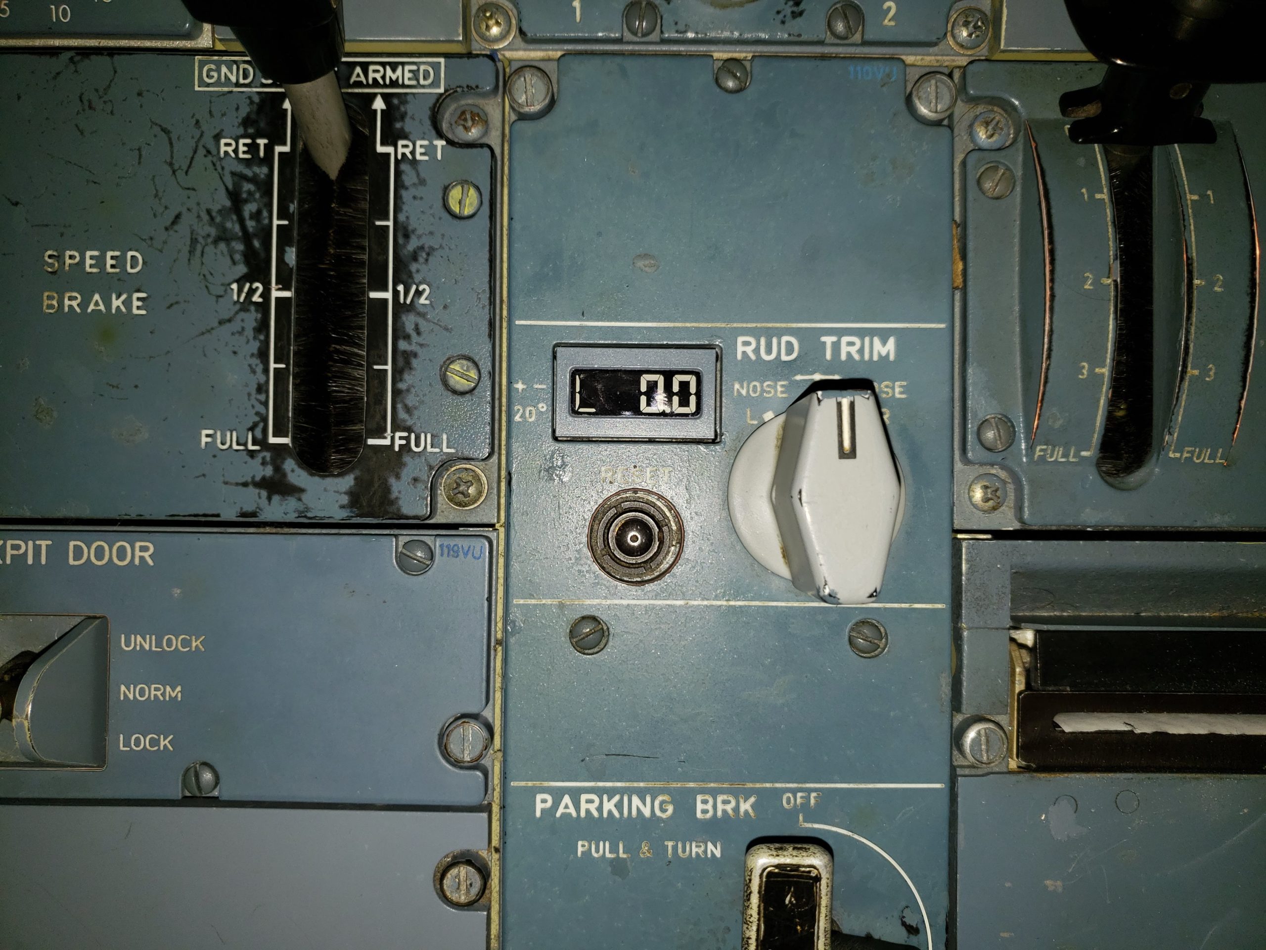
First, during manual flight, the system executes the trim order requested by the pilot through the RUD TRIM rotary selector (pictured above).
This moves the neutral point of the artificial feel unit by the equivalent of 1 degree of rudder travel per second.
Remember that the rudder can easily be reset to zero as well, simply by using the RUD TRIM RESET PB.
Secondly, when the autopilot is flying, trim orders originate within the FMGS and are then sent to the FACs.
This means that both the RUD TRIM rotary selector and the RUD TRIM RESET PB are inactive whilst the autopilot is engaged.

The A320 has two electric motors that trim the rudder.
These are the same motors used to control the artificial feel unit.
During normal operation, FAC 1 controls Motor 1 to power the rudder trim.
FAC 2 controls motor #2 and remains synchronized with FAC 1, ready to act as a backup.

Ready for your next Checkride?
Probably not as ready as you should be.
Certainly not as ready as you could be.
Click here to find out more about the world’s first and finest, complete emergency management system designed especially for the A320.
A failure of both FAC 1 and FAC 2 means that there’s no one left to control the rudder trim.
This means that you will no longer be able to control the rudder trim.
You’re FAC’d!
Don’t believe me?
Check it out!

In most cases, pilots will only need to deal with the rudder trim on the A320 when a failure requires its use.
Powerplant failures are a common example of this, and require rudder trim to combat the resulting thrust asymmetry.
Here are some helpful tips based on the observation of hundreds of crews:
A common mistake made by players of all ages is to try to engage the autopilot while the rudder is out of trim.
Here’s what it looks like:
- Engine fails.
- Pilot steps on and holds rudder, but doesn’t trim it out.
- Pilot engages autopilot and then promptly releases rudder pressure.
- Aircraft experiences a violent yaw swing and autopilot disengages.
- The Check Captain’s iPad goes flying through the simulator, hits the back wall and shatters.
- Check Captain is most unpleased and begins taking notes.
It’s a pretty sloppy look and is bound to earn you some special comments.
So there you go.
I hope you’ve enjoyed our look into how the FACS control the rudder trim in the A320.
As far as flight control computers go, the FACs don’t always get the attention they deserve, but make no mistake, they’re pretty important and anyway, every little bit of info helps to make your understanding of the machine clearer and more complete.
And that’s a good thing.
Be kind, be smart, fly well.
Until next time…

G’Day BusDriver!
Thanks again for another great comment!
I can certainly attest to your first point as there were many in a company I used to work for who would trim the rudder out during a Single Engine Taxi.
As you say, you’ve just got to make sure that the Rudder Trim has been reset to zero, which usually (and hopefully) gets picked up during the After Takeoff Checklist.
I couldn’t find the Nosewheel Steering Offset Procedure you mention.
Granted, I only spent a minute looking, but if you have an FCOM/FCTM reference, let me know as I’d love to check it out.
Cheers Mate,
© The A320 Insider. All Right Reserved
ATA 22: Airbus A320 (Technical Notes)
A320 ATA 22 Technical Notes are brief and to-the-point information about the Airbus A320 Auto Flight System, including its components and their functions. ATA Chapter 22 is titled Auto Flight, which covers automatic control of flight, including flight management, flight guidance, and flight augmentation.
A320 Auto Flight System
The Airbus A320 Auto Flight System is made up of the Flight Management and Guidance System (FMGS) and Flight Augmentation System (FAS).
The FMGS performs the functions: autopilot (AP); flight director (FD); autothrust (A/THR); and flight management, which includes navigation, performance, and processing of displays.
The FAS performs the functions: yaw damper; rudder travel limiting; monitoring of the flight envelope and computations of maneuvering speed; yaw autopilot order using power loops of yaw damper and rudder trim; and BITE function of the AFS by FAC 1.
AUTO FLIGHT – TECHNICAL POINTS
- Electrical Flight Control System (EFCS) to control flying surfaces, and
- Full Authority Digital Engine Control (FADEC) to control engines.
- Side Sticks, and sends them to EFCS to control flying surfaces.
- Thrust Levers, and sends them to FADEC to control engines.
- During AFS operation, side sticks and thrust levers do not move automatically.
- If the pilot moves the side stick when the AFS is active, it disengages the autopilot. Back to manual flight, when the sidestick is released, the EFCS maintains the actual aircraft attitude.
The Auto Flight System (AFS) is divided into four main parts:
- Flight Management (FM) – function accomplished by FMGCs.
- Flight Guidance (FG) – function accomplished by FMGCs.
- Flight Augmentation – function accomplished by FACs.
- Fault Isolation and Detection System (FIDS) – function accomplished by FAC1.
AFS is designed around –
- 2 FMGC – Flight Management and Guidance Computer
- 2 FAC – Flight Augmentation Computer
- 2 MCDU – Multipurpose Control and Display Unit
- 1 FCU – Flight Control Unit
To meet the necessary reliability, the AFS is built around 4 computers. There are two interchangeable Flight Management and Guidance Computers (FMGCs) and two interchangeable Flight Augmentation Computers (FACs). It is a FAIL OPERATIVE system. Each FMGC and FAC has a command (CMD) part and a monitor (MON) part to be FAIL PASSIVE.
Both FACs are interchangeable. FIDS function accomplished by FAC 1. Pin Programming for FIDS is on the interface (where FAC1 connects) not on the FAC (computer).
FMGC – TECHNICAL POINTS
FMGC performs the functions given below –
- Computation of position
- Radio navigation tuning
- Alignment of Inertial Reference System
- Management of Flight Plan – Construction and Follow-up
- Optimizing flight plan to reduce cost
- Predictions for primary and secondary flight plans and display them on MCDU & ND.
- Management of display on MCDU/PFD/ND
- Flight Director
Flight Management has four modes of operation:
- Normal Mode – Dual Mode (Both FMGC)
- Independent Mode – Each FMGC is controlled by its associated MCDU
- Single Mode – using one FMGC only
- Back-up Navigation Mode – in case both FMGC fails (optional system)
Flight Guidance
- Managed modes – Long-term pilot orders are entered through the MCDU.
- Selected modes – Short-term pilot orders are entered through the FCU.
- Selected guidance always has priority over managed guidance.
AUTOPILOT (AP)
- Stabilizes the aircraft around its center of gravity,
- Acquires and tracks a flight path, and
- Flies the aircraft to an automatic landing or go-around.
- If the airfield is equipped with ILS installations, the AP can perform a complete landing with approach, flare and roll out. >> AUTO LAND (AP engaged in LAND mode).
- the position of the control surfaces on the three axes: pitch, roll and yaw.
- the position of the nose wheel.
- These orders are taken into account by these computers: FACs, ELACs, SECs and BSCU.
- Lateral modes – guide the aircraft in lateral path.
- Vertical modes – guide the aircraft in vertical path.
- Basically, one of each mode is chosen by the pilot or by the system.
- Ailerons via the ELACs,
- Spoilers via the ELACs and SECs,
- Rudder via FACs,
- Nose wheel via the ELACs and BSCU.
- Vertical mode controls the elevators and the THS via the ELACs.
- The AP being engaged, one lateral mode and one vertical mode are simultaneously active.
- by means of the AP1 and AP2 p/b switches on FCU.
- AP1 has priority, AP2 is in standby.
- For maintenance purposes, AP can be engaged on ground with both engines shut down. When an engine is started, the AP disengages.
- When the AP is engaged, the load thresholds on the rudder pedals and the side sticks are increased. If a pedal or side stick load threshold is overridden, the AP disengages.
- Presses the takeover pb on the sidestick, or
- Presses the corresponding AP pb on the FCU, or
- Pushes on the sidestick harder than a defined threshold, or moves on the rudder pedals beyond a defined threshold.
- The standard way for the flight crew to disengage the AP is to press the takeover pb on the sidestick.
- The side stick controllers do not move when the autopilot is engaged.
FLIGHT DIRECTOR (FD)
- FD displays the guidance commands on both PFDs, allowing the pilots to fly the aircraft manually according to the FMGC demands. Two cases have to be considered –
- AP not engaged : FD function displays symbols on the PFD which gives orders to the pilot to maintain the desired parameters. In this case, the pilot follows these orders by acting on the flight controls.
- AP engaged : FD function displays symbols on the PFD representing the AP orders to be monitored by the pilot.
- FD1 displays FMGC1 orders on the PFD1, and
- FD2 displays FMGC2 orders on the PFD2.
- The FDs are engaged automatically when the FMGC powers up.
- The flight crew may disengage one or two FDs manually.
- FDs may disengage automatically if there is a failure.
- The FD pb on the EFIS control panel allows the FD bars to be displayed or removed.
- FD is only a display system, not controlling anything – guidance only.
AUTOTHRUST (A/THR)
- A/THR function can be ENGAGED or DISENGAGED.
- When it is engaged, it can be ACTIVE or NOT ACTIVE.
- ACTIVE – A/THR system controls the engines,
- NOT ACTIVE – Thrust levers control the engines as long as a thrust lever is outside the A/THR active area,
- Thrust levers control the engines, when A/THR function is disengaged.
- FADECs compute the thrust limit, depending on the position of the thrust levers.
- Thrust levers are manually operated and electrically connected to FADEC.
- A/THR has two systems, one per FMGC – A/THR 1 & A/THR 2.
- Auto engage – when some conditions are fulfilled.
- Manual engage – A/THR p/b on FCU.
- A/THR can operate independently or with the AP/FD.
- Both A/THRs are always engaged at the same time but only one is active depending on AP and FD engagement status.
- THRUST mode
- SPEED/MACH mode
- RETARD mode
- Pressing A/THR instinctive disconnect switch on any thrust lever, or
- Setting all thrust levers to idle position, or
- Pressing A/THR P/B on FCU.
- A/THR is automatically disengaged in case of failure detection.
- When the A/THR function is active, the actual engine thrust does not necessarily correspond to the thrust lever position. >> Thrust Lever does not move.
MCDU & FCU
- MCDU permit to enter and display a flight plan and the control parameters required by the FMGCs for flight control.
- FCU transmits the modes and the references selected by the pilots to the FMGCs.
- One for the automatic flight controls and
- Two for the Electronic Flight Instrument System (EFIS).
- The FCU consists of two identical computers totally independent.
FAC – TECHNICAL POINTS
FAC performs the functions
- Yaw damping – by using yaw dampers
- Rudder trim – manual or automatic
- Rudder travel limitation
- Flight Envelope Protection
- BITE function of the AFS in FAC 1 (FIDS)
- Yaw damper has four functions and controls the rudder via yaw damper actuators.
- dutch roll damping,
- turn coordination in cruise,
- engine failure compensation in auto flight,
- yaw guidance order execution.
- There are two yaw dampers. In normal operation, both are engaged but only one is active.
- The yaw damper actuator does not move the rudder pedals.
- Yaw damper actuator 1 – Green hydraulic system.
- Yaw damper actuator 2 – Yellow hydraulic system.
- Yaw Damper Position Transducer Unit.
RUDDER TRIM
- Manual trim with RUD TRIM selector,
- Auto trim on yaw axis and the generation of engine failure recovery function when the autopilot is engaged.
- Rudder trim orders come from the Rudder Trim Selector Knob via FAC to control the rudder via the Rudder Trim Actuator.
- When the AP is engaged, the rudder trim selector knob is inoperative, – FMGC sends rudder trim orders to the FAC.
- Rudder Trim Reset P/B Switch
- Rudder Trim Indicator
RUDDER TRAVEL LIMITING
- Limits the deflection for structure integrity,
- Prevents excessive deflections which would penalize the aircraft performance.
- The rudder travel limitation is computed by the FAC and sent to the Rudder Travel Limiting Unit (RTLU).
FLIGHT ENVELOPE PROTECTION
For flight envelope protection, the FAC computes:
- Various speeds for aircraft operation (e.g. flaps limit speed),
- ACTIVE WINDSHEAR – Protection by FAC.
- PREDICTIVE WINDSHEAR – Protection by PWS function in WXR.
- Alpha-floor detection to the FMGCs for A/THR engagement, if it is not engaged,
- Low energy warning, indicating to the crew that the aircraft is quickly decelerating and that thrust will have to be increased to recover a positive flight path angle through pitch control, – “ SPEED SPEED SPEED “
- Warning for Tail Strike Protection. “ PITCH-PITCH “
- FAC also computes the weight and the center of gravity.
FAC 1: BITE Function
- FAC 1 is connected to the BITE of all the AFS computers and communicates to the CFDS.
- FIDS card is physically located in the FAC1 and is activated.
- FIDS serves as the SYSTEM BITE (maintenance data concentrator).
- The FIDS is linked in acquisition and reception to the centralized fault-display interface-unit (CFDIU) and is connected to the BITEs of the various AFS computers.
A320 Auto Flight Schematic

- FMGC – 2
- FAC – 2
- FCU – 1
- MCDU – 2
See the location of A320 Computers .
CONTROLS AND INDICATIONS
- FLIGHT CONTROL PANEL
- FLIGHT CONTROL UNIT
- EFIS CONTROL PANEL
- THRUST LEVER & PITCH TRIM
- INDICATIONS ON PFD
- INDICATIONS ON ND
THRUST LEVERS
The thrust levers can be moved on a sector which includes specific positions:

- Rear section: for idle reverse up to max reverse.
- 0: corresponds to an idle thrust,
- CL: corresponds to a climb thrust.
- FLX/MCT: corresponds to a FLeXible take-off thrust or a Maximum Continuous Thrust after an engine failure,
- TOGA: corresponds to a maximum Takeoff/Go Around thrust.
OTHER POINTS
Fms aoc functions.
The Flight Management System (FMS) AOC function serves as an interface between a ground station and an onboard Flight Management and Guidance Computer (FMGC). It allows data exchange between these two computers via either the Aircraft Communications Addressing and Reporting System (ACARS) Management Unit or the Air Traffic Services Unit (ATSU).
Two different sets of messages can be exchanged:
- UPLINK messages originate from the ground station. They involve receiving requested data or direct communication with the flight crew.
- DOWNLINK messages originate from the FMGC (acting as the master). These messages include reports or requests sent to the ground station.
The FMGS/ACARS or FMGS/ATSU interface enables several AOC (Aircraft Operations Control) capabilities, including:
- F-PLN initialization (setting up the flight plan and performance data).
- Takeoff data management.
- Wind data handling.
- Flight reports generation.
- Broadcast data dissemination.
Crews can send messages using the ACARS FUNCTION pages or relevant MCDU (Multipurpose Control and Display Unit) pages. Importantly, only one FMGC communicates with the ground station, and this specific FMGC is known as the FMGC master.
FLIGHT PLANNING
FLIGHT PLANNING > FLIGHT MANAGEMENT DATABASES
- Navigation Database – contains standard navigation data like navaids, waypoints, airways, enroute information, and airports.
- Performance Database – contains aircraft performance related data. Airlines can modify this database.
FLIGHT PLANNING > ACARS FUNCTION
- The Flight Management uses the Aircraft Communication Addressing and Reporting System (ACARS) function to exchange data between the ground station and FMGC via the ATSU.
- This interface makes the exchange of flight plan initialization, take-off, wind, and broadcast data and flight reports with the ground. Via the ACARS, the crew may send a request for wind data to the ground. In response to this request, or automatically, the ground sends climb, cruise, descent and alternate wind data to the aircraft.
EFIS DISPLAYS
- Four EFIS displays, i.e. two PFDs and two NDs.
- Flight parameters are displayed on the PFDs.
- Flight plan and navigation data are displayed on the NDs.
- FMA is the top part of the PFD.
FLIGHT MODE ANNUNCIATOR (FMA)
- A/THR mode/status,
- AP/FD mode and status,
- Flight Management (FM) messages.
- FMA Comprises 3 lines and 5 column
APPROACH MODE
The aircraft can fly different types of approaches:
- Precision approaches: ILS, (MLS – Military).
- Non-precision approaches: VOR/DME, VOR, NDB (if ADF), RNAV.
- Non-precision approaches using a Localizer only: LOC.
LANDING CAPABILITIES
Each FMGC computes its own automatic landing capability.
- FMA displays “CAT 1”, “CAT 2”, “CAT 3 SINGLE” or “CAT 3 DUAL”.

Our team at AviationHunt is a group of aviation experts and enthusiasts. We aim to provide aviation insights, technical notes, best aircraft maintenance practices, and aviation safety tips.
Leave a Reply Cancel reply
Your email address will not be published. Required fields are marked *
Save my name, email, and website in this browser for the next time I comment.
- You are here
- Everything Explained.Today
- A-Z Contents
- Rudder travel limiter
Rudder travel limiter explained
A rudder travel limiter , or rudder limiter , is a controlling device in an aircraft used to mechanically limit the maximum rudder deflection.
An aircraft rudder is a flight control surface used to control rotation around its vertical axis, known as yaw, [1] which is especially important during takeoff, landing, and emergency conditions. Rudders are typically found within the vertical stabilizer of the aircraft. Excessive use of rudder can exceed the ultimate load of the vertical stabilizer, causing structural failure. [2] For this reason, modern airliners and fly-by-wire aircraft often include a system to prevent excessive rudder deflection.
The rudder travel limiter in the Airbus A300-600 is controlled by the Feel and Limitation Computers (FLC) maintaining sufficient yaw control within the entire flight envelope and limiting excessive lateral loads on the rudder and vertical stabilizer . [3]
Notable Accidents
A fault with the rudder travel limiter was involved in the crash of Indonesia AirAsia Flight 8501 . The design of the rudder travel limiter on the Airbus A300-600 was cited as a contributing factor to the crash of American Airlines Flight 587 . In addition to a low rudder pedal sensitivity compared to other aircraft, the A300-600 had a variable stop design, contrary to earlier iterations of the A300, which used a variable ratio design. [4]
Notes and References
- Web site: Rudder . SKYbrary Aviation Safety . 27 July 2020.
- News: Bellamy . Woodrow . AirAsia Flight 8501 Crash Caused by Pilot Error, Rudder Units . 27 July 2020 . Aviation Today . 3 December 2015.
- Web site: Use of rudder on Airbus A300-600/A310 . IFALPA . December 2010. 1 December 2015.
- In-Flight Separation of Vertical Stabilizer American Airlines Flight 587 Airbus Industrie A300-605R, N14053 Belle Harbor, New York November 12, 2001 . October 26, 2004. National Transportation Safety Board. NTSB/AAR-04/04. July 3, 2017. https://web.archive.org/web/20170430010317/https://www.ntsb.gov/investigations/AccidentReports/Reports/AAR0404.pdf. April 30, 2017. ntsb.gov. live.
This article is licensed under the GNU Free Documentation License . It uses material from the Wikipedia article " Rudder travel limiter ".
Except where otherwise indicated, Everything.Explained.Today is © Copyright 2009-2024, A B Cryer, All Rights Reserved. Cookie policy .
- Limitations
- Standard Operating Procedures
- Airliner Flying Guide
- Terms and Abbreviations
- Development Corner
- Release Notes
ECAM F/CTL page
Back to ECAM System Display Overview

Defense Daily subscriber and registered users, please log in here to access the content.
Email or Username
- FREE E-Letters
- Publications
- Contracts – FREE ACCESS
- Defense Daily Issue Archive
- Career Center
- Advertise With Us
Rudder System Recommendation Could Portend More to Come
A recommendation to modify the Airbus A300-600 rudder travel limiter (RTL) to prevent excessive aerodynamic loads could be the first of more calls to improve the airplane’s rudder control system.
The National Transportation Safety Board (NTSB) issued a May 28 recommendation based on its findings that the RTL did not limit rudder movement as designed when an American Airlines [AMR] A300-600 involved in a 1997 stall event experienced rapid airspeed changes that outran the limiter’s ability to keep up. As a result, the tailfin was stressed beyond ultimate load, which eventually required replacement of the composite tailfin. Ultimate load is the 50 percent safety factor added to limit load, which represents the greatest force expected to be encountered in service. The incident airplane, operating as Flight 903 at the time, experienced rudder reversals as a consequence of four rudder inputs in opposing directions. Reversals, or rapid rudder deflections from one side to the other without stopping at the neutral position, can induce yawing that places great stress on the tailfin, rapidly building aerodynamic forces the fin was not designed to withstand.
Another American A300-600 operating as Flight 587 experienced a series of rudder reversals in November 2001, leading again to ultimate load and, this time, to fin separation. The airplane crashed into Belle Harbor, N.Y., killing all 260 aboard and five persons on the ground. It was one of the deadliest crashes in North American aviation history. NTSB sources close to the Flight 587 investigation tell ASW that additional rudder design recommendations are likely.
The Flight 587 crash has locked American Airlines and Airbus into a heated dispute. Airbus claims the copilot flying the aircraft mishandled the rudder system by imparting a series of rapid and inappropriate reversals. American counters that the reversals were the inevitable result of an overly sensitive and flawed rudder control system design (see ASW, March 29).
The NTSB recommendation focuses on the Flight 903 event, saying that in cases of rapid airspeed changes the RTL cannot keep up with the rate of change. Therefore, the rudder could travel beyond the 14.5� deflection limit established for an airspeed of 220 knots (the deflection limit decreases with an increase in airspeed). The Flight 903 stall upset involved an airspeed change from 190 to 220 knots in the span of some three seconds. That is an airspeed change rate of 10 knots per second. In the 165-220 knot speed range, the limiter can “handle” airspeed changes of 2.4 knots per second and restrict rudder movement. However, the 10 knots per second airspeed change in the Flight 903 event was a rate some four times faster than the rudder travel limiter could respond.
Because of this, the NTSB said, “The rudder was allowed to travel in excess of its RTL design limit for approximately 20 seconds.”
Therefore, the NTSB wants the Federal Aviation Administration (FAA) to require Airbus to modify the RTL so that it can respond “effectively to rapid airspeed changes.”
A footnote in the NTSB’s recommendation letter said the safety issues emanating from the Flight 903 event were “not a factor in the Flight 587 accident.”
In effect, the NTSB appears to be disassociating Flight 903 and Flight 587 as two distinct and different events. Airbus officials have publicly seconded this point of view, claiming in response to the NTSB letter that the RTL modification has “nothing to do” with the Flight 587 accident.
However, the acceleration parameter is not viewed by all the participants as the dividing line between the Flight 903 upset and the Flight 587 crash. In its statement reacting to the NTSB letter, American Airlines said its rudder training – revised after the Flight 587 crash – “addresses specific characteristics of the rudder travel limiter system … that this NTSB recommendation involves.”
“These limitations, along with others related to the sensitivity of the system, are precisely the concerns American addressed in its final submission and recommendations to the NTSB regarding the Flight 587 accident,” the airline’s statement said.
The Flight 587 accident is unique in the sense that some American Airlines A300-600 pilots have organized themselves into a group, and they have issued various papers and recommendations during the investigation outlining their point of view (see ASW, June 17, 2002) . In response to this latest development, the pilot’s group declared, “As for the limiter failure being ‘separate’ from the AA 587 incident, this attempt to ‘parse’ this deficiency waters the eyes it is such a transparent obfuscation.” The A300-600 pilots group asserted that the investigation has uncovered evidence that the limiter failed twice on Flight 587, “including on the fifth rudder movement.”
One of the most contentious issues concerns the series of opposing rudder movements imparted in the space of some seven seconds on the Flight 587 accident aircraft. Airbus has contended that American’s upset recovery training predisposed pilots to make excessive use of the rudder.
This issue of pilot rudder use in the Flight 587 crash may not necessarily be separable from pilot actions in the Flight 903 upset. In that 1997 event, NTSB investigator John O’Callaghan wrote in the aircraft performance study that ailerons were coordinated with the rudder to arrest the airplane’s increasing bank angle, which approached 70�. O’Callaghan’s report said four large left-to-right rudder inputs were made before the first stall “which generated large rolling moments.” However, his report went on to say, “the initial continued right roll against left control inputs prior to the first stall … is inconsistent with the expected behavior of the aircraft and justifies use of the rudder to help stop the roll.”
This statement can be interpreted by the parties involved in two ways: (1) that the Flight 903 pilot’s use of rudder to recover was appropriate to the situation, as was that of the Flight 587 pilot four years later, which is the American position, or (2) that the rudder inputs in Flight 903 were conditioned by American’s training program on rudder use, with fatal consequences for Flight 587, as Airbus maintains.
American officials do not dispute that the Flight 587 pilot applied four opposing rudder commands initiated as he attempted to arrest the airplane’s increasing left bank during the second wake vortex encounter with a Japan Air Lines B747 that had taken off just shortly before Flight 587 roared down the same runway at New York’s John F. Kennedy International Airport.
But where American differs with Airbus is that the rudder system’s sensitivity made fine modulation of rudder movement impossible. The American argument is that the pilot flying, Sten Molin, attempted to use the rudder to assist in roll control but he got a 9.3� deflection in a split second, and within six seconds of his subsequent input attempts to right the airplane the tailfin snapped off.
Indeed, with 130-140 pounds of pressure on the pedals, pilots can achieve additional rudder movement. Airbus officials have referred to this as “elasticity,” implying not a design deficiency but a heavy-footed pilot deficiency.
Two particulars of the case suggest that the NTSB may have more to say about the A300-600 rudder control system as the Flight 587 investigation moves to its expected conclusion later this year.
O’Callaghan chaired the aircraft performance study in the Flight 587 investigation. His analysis of the A300-600 rudder control system concluded that the pilot can “override” the yaw damper at the rudder travel limits. The yaw damper is designed to attenuate directional oscillations, thereby suppressing the buildup of sideslip angle and resulting aerodynamic forces on the tailfin. O’Callaghan’s report provides an example of yaw damper override. If the RTL limit is 10� right, and the pilot pushes the pedal for 10� right rudder, and the yaw damper commands 2� of left rudder, the right10� right rudder command is reduced to 8�. However, the mechanical linkage is such that the pedal moves back slightly, which in this case gives the pilot another 2� of pedal travel. Therefore if the pilot maintains pressure, the resulting output command to the rudder will be 10� right, regardless of yaw damper input, according to the O’Callaghan report.
Data culled from the accident airplane’s flight data recorder (FDR), O’Callaghan reported, “suggest that this suppression of the yaw damper inputs at the rudder limits probably occurred during the accident flight.”
An NTSB source explained that the design allows for higher aerodynamic loads on the tailfin than would be the case in a rudder control system where the yaw damper cannot be overridden.
O’Callaghan’s team explored an alternative design layout, in which the pedals are limited separately. This architecture was dubbed a “pedal limiter” system. In this arrangement, the yaw damper cannot be overridden and there would be no additional pedal motion to push the rudder back to the limit. A computer simulation of the Flight 587 scenario showed a “noticeable” reduction in the lateral load factor on the airplane. Interpreting the graphic results in the report suggests about a 23-25 percent reduction of sideslip angle and about 20 percent in lateral G loading.
Having entertained an alternative design that reduces potentially dangerous aerodynamic loads on the tailfin, it seems unlikely that the NTSB would fail to recommend implementation.
For another thing, the NTSB commissioned an independent review of the A300-600 rudder system. Conducted by Dr. Ronald Hess, vice chairman of the Department of Mechanical and Aeronautical Engineering at the University of California , Hess concluded that the pedal/rudder sensitivity of the A300-600 was seven times greater than that of the Boeing [BA] B767, a comparable design. In comparison to the A300-600B2/B4 series aircraft, which preceded the A300-600 series, and at the 250-knot airspeed at which the Flight 587 accident occurred, Hess reported “the A300-600 exhibits over six times the yaw acceleration per pound of pedal input of the B2/B4 series.”
Hess concluded that the system’s sensitivity was conducive to pilot-induced oscillation (PIO), which he asserted “was evident in the moments before the crash.” The essential characteristic of a PIO is that the airplane’s control characteristics can cause the pilot’s attempts to restore stability to be out of phase with the aircraft’s response. Instead of dampening yaw excursions, as in the Flight 587 case, rudder pedal movements unintentionally were reinforcing them. The analogy may be the effortless synchrony required to maximize the height-gain of a child’s playground swing.
The French accident investigation body, the Bureau d’Enquetes et d’Analyses pour la S�curit� de l’Aviation Civile (BEA), countered that Hess’s analysis was flawed. “As far as we know, no studies have been undertaken on PIO on the yaw axis since the rudder is not a primary flight control,” the BEA said. Noting that the Flight 587 pilot used rudder inputs in an attempt to arrest the airplane’s left roll, the BEA said “even a light rudder pedal input may create a divergent output,” adding, “This system remains stable simply by using the control wheel with high gain.” This remark captures the essence of the Airbus position that if the pilot had kept his feet off the rudder pedals the accident would not have happened.
Since the NTSB commissioned Hess’s report, and Hess is a recognized expert in aircraft stability, control and PIO issues, it does not seem likely that the board will reject outright his findings and their implications for design changes.
These aspects of the rudder system design from the Flight 587 investigation indicate that the recent recommendation on the RTL emanating from the Flight 903 event represents an effort to put the airspeed change vulnerability to bed. The action could be interpreted as clearing the way to focus on the control sensitivity and yaw damper override issues brought to light in the Flight 587 crash investigation.
The accident pilot and American’s upset recovery training may not yet be absolved by any means, but neither may be the A300-600 rudder control system.
Recommended
Safety board calls for design changes to airbus rudder system, american airlines tries to pin blame on design defect, the conundrum of american airlines flight 587.
- Diversity, Equity, Inclusion & Belonging
- Accessibility Statement
Featured Categories
- Advanced / Transformational Technology
- Business/Financial
- Force Multipliers
- Homeland Security
- Intelligence Community
- International
- Missile Defense
- Nuclear Modernization
- Partner Content
- Press Releases
- Special Operations
- Unmanned Systems
Your cart is empty
Estimated total.
Welcome to our new website
ToLiss A320 NEO
Collapsible content, v1.0.4 - december 5, 2023.
Changes from V1.0.3 (build 1596) to V1.0.4 (build 1600) New feature: - New ISCS option to allow rudder pedals to fully deflect the nose wheel in VR mode in XP12. Bug fixes: - Corrected position of the dome light source - Fixed flare law type (back to old flare law, while maintaining the TO rotation and landing derotation laws) - Fixed issue with EFB TO Performance calculator when using AUTO flap setting. - Fixed issue with managed speed target during touch and goes. - Fixed a bug with the date on Wind and Flight plan data printouts
V1.0.3 - November 5, 2023
Changes from V1.0.2 (build 1584) to V1.0.3 (build 1596)
This version has lots of new system functionality, like better FADEC simulation, hydraulic overheat faults and more bringing the total of functional circuit breakers up to 221! There are also tons of bug fixes following user and pilot feedback making this our most accurate representation of the A320 family aircraft yet!
The detailled change log is as follows: New features: - Added new C/Bs bringing the total number of functional C/Bs to 221 - New faults: Yaw Damper, Rudder Travel Limiter, Rudder Trim - New faults: Hydraulic system overheat - FADEC needs 2-3 seconds to power up - Popout windows now remain visible in external view - ATIS requests via the Hoppie network can now also query the PilotEdge network - New failure modes: FADEC faults - Reordered ECAM messages to represent newer FWC standard - ACP knobs are now moving up and down - Added Ignition failures to ECAM. (Use C/Bs to disable ignition) Bug fixes: - Corrected labelling issues in Overhead panel and on rear C/B panels. - Prevented G/S mode engagement with both ratio altimeters failed - Improved sounds during replay - Corrected the arrangement of the Taxi and TO lights in the nose landing gear. - Adapted center tank fuel pump configuration to the new standard - Changed FMA indication to maximum of CAT 2 when A/THR is not engaged. - Brought TRx INOP status message back on SD Status page. - Fixed HYD Page PTU color when conditions for PTU to operate are not met. - Round metric FCU altitude on PFD to 10m - Improved FAC FAULT ECAM actions - Added 3s timeout when pressing the status page with status "NORMAL". - Use FMGS weights for VLS if initialized. - Reworked behaviour of the FAC cutout switches - MCDU APPR speed predictions take current weight, when approach phase active. - PTU should not be able to power circuits without fluid anymore - with dual RA fault, LG not down warning should trigger with flaps 3 or 4 - improved go around engagement logic, to all GA engagement also in climb phase. - Improved ISCS open/closing in VR - Removed armed NAV mode when performing a TO without FDs. - Prevent overwriting of cruise waypoint wind data when reaching TOC or initiating S/Cs. - Improved contour matching for artificial cockpit window reflections - Fixed managed speed profile in Go Around after acceleration altitude - Simbrief wind upload should work again. (Note that it extracts the data from the wind data field, not from the flight plan itself.) - Fixed number of blades in the PW1100G engine. - Improved bleed pressure at cruise - Improved altitude alert logic (C chord and flashing frame) - Fixed logic for ELAC/SEC reversion to backup power supply - Maintain VHF selection in the RMPs during power transients - Improved Dept RWY remapping on situation load - Improved logic for MCDU class II messages
V1.0.2 - June 29, 2023
Changes from V1.0.1 (build 1577) to V1.0.2 (Build 1584) Minor new features: - Added engine sound blending at high altitudes and Mach number for more realistic sound experience in the cockpit in cruise - Full support for the new XP12 copilot joystick axes including separate in-cockpit animations if these axes are assigned - Radioaltimeter failures are now available Bug fixes: - Fixed some issues with the new cockpit textures - Improved the new engine sounds (removing of phasing, better sound in aft cabin) - Improved the new external pack sound (previously labelled APU Bleed sound) - Added autopilot disconnection on manual trim. - Reduced minimum valid preselected speed to allow speeds below 160kts. - Improved mouse wheel pitch trim speed - Fixed FMGS bootup when starting on ground with external power applied or APU running. - Fixed the issue that when launching an emergency evacuation the doors were waiting for the ground vehicles to open - Fixed a bug with the descent profile following if below transition level and QNH in MCDU and QNH on FCU don't match - Fixed the on-ground rotation law - Some improvements to the smartcopilot.cfg file - Fixed a bug that caused the GS Mini not to be considered with pilot selected VAPP. - Fixed jitter of the L/DEV and V/DEV scales that can occur under certain conditions when performing a GA during a non-precision approach
V1.0.1 - May 5, 2023
Changes from V1.0 (build 1572) to V1.0.1 (build1577) Major new features: - Major sound rework - Native M1 support on iMac Minor new features: - Oil temperature indication on ECAM now changes according to logic specific for the given engine type - Increase landing gear tire resolution for a rounder experience - Added console lights (XP12 only) - Increase number of possible simultaneous faults to 20 - Added PRED WS OFF memo - Automatic reversion to arrival or departure ATIS request if regular ATIS is not available (via Hoppie network) - Added animated sunblinds - Added animated stairs on the left side. Bug fixes: - Fixed ISCS not working correctly on multi monitor setups - Corrected oil temperature speed of change - Corrected the logic for the required cooling time on the PW1100G engines - Inhibit of EGT OVERLIMIT warning following an engine shutdown due to fire - Brought the REV SET ECAM Caution back - Adapted belly fairing shape - Improved tire rotation animation - Fixed the missing inner flap track fairing when multifunction runway lights are selected - Fixed UV mapping issue on the outflow valve - Improved wing scan light visibility at daytime. - Fixed upper beacon position in XP11 - Fixed mouse wheel function on WX Radar System switches - Fixed XP11 librain rain effects - Fixed FBW behaviour in case of loss of both FAC (no reversion to direct on L/G extension) - Fixed FBW upmode logic to allow automatic upmode to normal law if conditions triggering a degenerated law are gone. - Fixed link between APU start capability and battery availability - Improved VLS computation in dual hydraulic cases with slats frozen in the retracted position. - Improved rudder authority for VMGC and Beta target - Improved MCDU and FMGC startup sequence on ground - Fixed a crash in PDC/CPDLC messages if there are space characters in the wrong spot. - Fixed a bug with fuel consumption during 200NM jumps
V1.0 - March 20, 2023
The ToLiss A320 NEO is released !
- Choosing a selection results in a full page refresh.
- Opens in a new window.
- › Air Law
- » A320
- » A330
- » A340
- » A350
- » B717
- » B737NG
- » B747
- » B777
- » E-Jet
- › Airlines
- › Aviation Theory
- › Crew Deals
- › Operational Information
- › Help & Information
Online Apps
- › Contact Us
- [a330:rudder]
Rudder and pedal deflections are limited as a function of speed via a rudder travel limiter. The limits are shown on the F/CTL page . The RUD TRIM rotary switch is not active during flight with the autopilot engaged.
To test the rudder pedals, the PEDALS DISC button on the nose wheel steering handle must be pressed and held.
In a total loss of electrical power or total loss of flight control computers the BYDU becomes active.
Yaw damping is a function of the flight control computers. After total electrical failure or loss of rudder control due to flight control computer failure, the BCM provides yaw damping.
Categories : Airbus A330 | Flight Controls
Powered by cWiki @ Aviaddicts
2018 Primetime Emmy & James Beard Award Winner
R&K Insider
Join our newsletter to get exclusives on where our correspondents travel, what they eat, where they stay. Free to sign up.
A History of Moscow in 13 Dishes
Featured city guides.
IMAGES
VIDEO
COMMENTS
A rudder travel limiter, or rudder limiter, is a controlling device in an aircraft used to mechanically limit the maximum rudder deflection. Background. An aircraft rudder is a flight control surface used to control rotation around its vertical axis, known as yaw, which is especially important during takeoff, landing, and emergency conditions.
12. The KNKT's final report on last year's Air Indonesia QZ-8501 crash repeatedly mentions that the faulty solder joint on the Flight Augmentation Computer (FAC) caused an open circuit on "both channel A and B", leading to the repeated failure of the Rudder Travel Limiter Unit (RTLU). (Page 66 of the report has a photo of the offending solder ...
The FAC transmits the ELAC rudder deflection orders to the Y/D actuator and achieves the Rudder Travel Limit function. Role of the "Yaw Damper" on FBW aircraft: A330. and A340. The "Yaw Damper function is actually part of the Lateral Normal Law, as achieved by the PRIM. The Lateral Normal Law main objective is to command a Side Slip (ß ...
Last. Tech Log - A320 Rudder Trvel Limit. - The A320 FCOM says "Regardless of the aircraft speed, therefor the maximum rudder deflection , full ruder pedal travel remains available. However, except at low speed, maximum rudder deflection is achieved before reaching maximum rudder pedal travel" what do they mean by.
2. Yes, A320 and all newer models have rudder travel limiter that limits the maximum rudder deflection depending on speed. It should be noted, that this has nothing to do with normal law. Normal law governs pitch and roll. Rudder is controlled by (hydro)mechanically connected ¹ pedals and yaw damper, which is independent from the system ...
By David Kaminski-Morrow 7 April 2021. Airbus is aiming to replace the mechanical rudder controls on A320neo-family aircraft, switching to a full electric rudder system by early 2024. The ...
I hope you've enjoyed our look into how the FACS control yaw damping in the A320. Don't forget the FACs also control other yaw related functions such as the A320's rudder trim and rudder travel limiter. We'll look at these in another training. Be kind, be smart, fly well. Until next time…
September 10, 2023. Written by TermAviation. Rudder Travel Limiting (RTL) is a crucial system in aviation that helps to ensure the safe and controlled operation of aircraft. It refers to the movement limits of the rudder, which is a primary control surface responsible for controlling the yaw, or side-to-side movement, of the aircraft.
How do the FACs control the rudder trim in the A320? The A320 has two electric motors that trim the rudder. These are the same motors used to control the artificial feel unit. During normal operation, FAC 1 controls Motor 1 to power the rudder trim. FAC 2 controls motor #2 and remains synchronized with FAC 1, ready to act as a backup.
But constant fast rudder movements can lead to a very bad situation. Since the introduction of A300-600, Airbus started using variable stop rudder travel limiter systems. In a variable stop limiter, not only is the rudder deflection reduced with increasing speed, but also the pedal movement in the cockpit.
RUD WITH CARE ABV 160 KT L2 Depending on when the failure occurs, the rudder travel limiter system may not be in the correct position for the flight speed. Therefore, to prevent damage to the aircraft structure, use the rudder with care, when the speed is greater than 160 kt. At slats' extension, full rudder travel authority can be recovered.
A320 ATA 22 Technical Notes are brief and to-the-point information about the Airbus A320 Auto Flight System, including its components and their functions. ATA Chapter 22 is titled Auto Flight, which covers automatic control of flight, including flight management, flight guidance, and flight augmentation. Page Contents. A320 Auto Flight System.
Rudder travel limitation unit
A fault with the rudder travel limiter was involved in the crash of Indonesia AirAsia Flight 8501. The design of the rudder travel limiter on the Airbus A300-600 was cited as a contributing factor to the crash of American Airlines Flight 587. In addition to a low rudder pedal sensitivity compared to other aircraft, the A300-600 had a variable ...
The rudder pedal limiter will give a direct feel feedback of the allowed rudder travel as a function of speed: To start moving the rudder pedals from the neutral position, a mini-mum force of +/- 10 daN must be applied (′′breakout force′′). maximum travel which represents a 30 daN force applied on the pedals.
The rudder is operating normally. Amber color: The blue, green, and yellow hydraulic pressure is low. 9: Rudder travel limiter: Green color: The rudder travel limiter is operating normally. Amber color: The rudder travel limiters 1 and 2 are faulty. Amber TLU: The TLU indexes are suppressed: 10: Rudder trim position: Blue color: The rudder trim ...
A recommendation to modify the Airbus A300-600 rudder travel limiter (RTL) to prevent excessive aerodynamic loads could be the first of more calls to improve the airplane's rudder control system.. The National Transportation Safety Board (NTSB) issued a May 28 recommendation based on its findings that the RTL did not limit rudder movement as designed when an American Airlines [AMR] A300-600 ...
change log. ToLiss A320 NEO. Collapsible content. V1.0.4 - December 5, 2023. Changes from V1.0.3 (build 1596) to V1.0.4 (build 1600)New feature:- New ISCS option to allow rudder pedals to fully deflect the nose wheel in VR mode in XP12. Bug fixes:- Corrected position of the dome light source- Fixed flare law type (back to old flare law, while ...
Rudder Rudder and pedal deflections are limited as a function of speed via a rudder travel limiter. The limits are shown on the F/CTL page. The RUD TRIM rotary switch is not active during flight with the autopilot engaged. To test the rudder pedals, the PEDALS DISC button on the nose wheel steering handle must be pressed and held. Yaw damper ...
Thank you for watching my video on Moscow Russia! This was my first time to Moscow. After all my travels, I finally made it to Moscow Russia and couldn't bel...
Moscow International Business Center!The Moscow International Business Center (MIBC) (Russian: Московский международный деловой центр, tr. Moskovskiy mezhdun...
1: Off-kilter genius at Delicatessen: Brain pâté with kefir butter and young radishes served mezze-style, and the caviar and tartare pizza. Head for Food City. You might think that calling Food City (Фуд Сити), an agriculture depot on the outskirts of Moscow, a "city" would be some kind of hyperbole. It is not.
There are lots to see in the city centre of Moscow, so we decided to start our series of Russia travel videos by showing you around the most historical part ...